
key Takeaways
SOLIDWORKS: How to Use Chamfer
What is Chamfer?
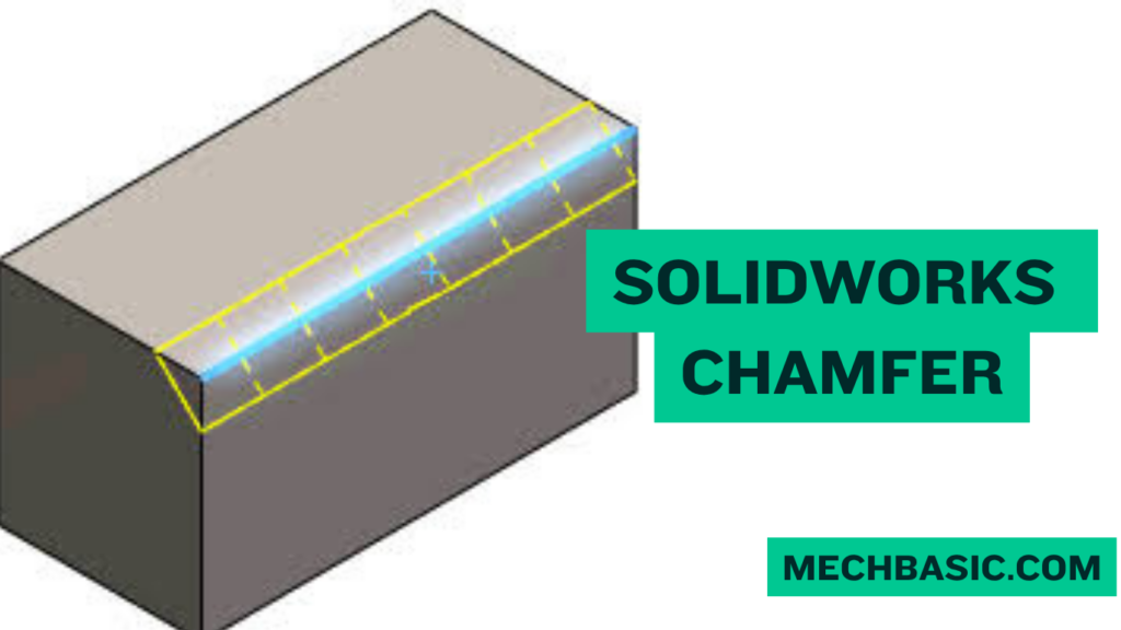
A Chamfer is a feature used to create a sloped or angled edge on a part instead of leaving a sharp edge. It is commonly used to improve safety, appearance, assembly, and manufacturability.
How to Create a Chamfer:
- Open the Part – Open the SOLIDWORKS model where the chamfer is required.
- Select Chamfer Tool – Go to Features → Chamfer.
- Select the Edge – Click the edge or edges that you want to chamfer.
- Set Chamfer Type – Choose Angle-Distance, Distance-Distance, or Vertex as required.
- Enter Dimensions – Specify the required distance and angle.
- Preview & Apply – Check the preview and click OK to create the chamfer.
Common Chamfer Types:
- Angle-Distance – Defines the chamfer using one distance and an angle.
- Distance-Distance – Defines two distances for the chamfer.
- Vertex – Creates a chamfer at a selected vertex.
Applications of Chamfer:
Chamfers are used to remove sharp edges, improve safety, assist component assembly, improve appearance, and prepare parts for manufacturing.
Key Takeaway
Select Edge → Chamfer Tool → Select Type → Set Dimensions → Preview → OK
In this article:
SOLIDWORKS: How to Use Chamfer
The Chamfer feature in SOLIDWORKS is used to create a beveled or angled edge on a 3D model. Instead of leaving a sharp 90° edge, a chamfer removes material at a specified angle and distance.
Chamfers are commonly used in mechanical parts, manufacturing components, holes, shafts, brackets, and assemblies to improve functionality, safety, and manufacturability.
What is Chamfer?
A chamfer is an angled cut made along an edge of a part.
For example, instead of this:
Sharp Edge
      |
      |
______|
a chamfer creates:
      |
      |
_____/
The chamfer can be defined using parameters such as:
- Chamfer distance
- Chamfer angle
- Two distances
- Selected edges or faces
Example
A 2 mm × 45° chamfer removes a 2 mm portion of the edge at an angle of 45°.
How to Create a Chamfer
Step 1: Create or Open a Part
Open an existing SOLIDWORKS part or create a new one.
For example:
New Part → Sketch → Extruded Boss/Base
Step 2: Select the Chamfer Tool
Go to:
Features → Chamfer
You can also find the Chamfer command from the appropriate SOLIDWORKS toolbar/menu.
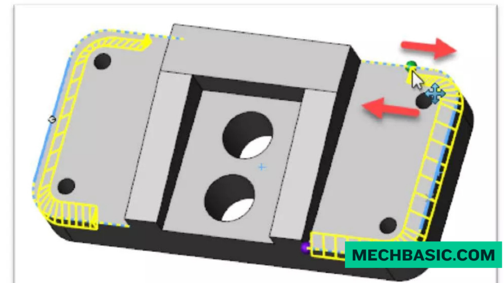
Step 3: Select the Edge
Click the edge that you want to bevel.
You can select:
- One edge
- Multiple edges
- A face
- Several connected edges
The selected geometry will appear in the Chamfer parameters.
Step 4: Select the Chamfer Type
Choose the required chamfer definition, such as:
- Angle-Distance
- Distance-Distance
The exact available options can depend on the SOLIDWORKS version and feature configuration.
Step 5: Enter the Dimension
For a common chamfer, enter:
Distance = 2 mm
Angle = 45°
You can preview the result directly on the model.
Step 6: Preview the Chamfer
Check the preview carefully.
Make sure:
- The correct edge is selected
- The chamfer direction is correct
- The dimension is appropriate
- The chamfer does not interfere with other features
Step 7: Click OK
Click the green check mark ✔ to create the chamfer.
The Chamfer feature will appear in the FeatureManager Design Tree.
Common Chamfer Types
1. Angle-Distance Chamfer
This is one of the most common methods.
You specify:
Distance + Angle
Example
2 mm × 45°
This means the chamfer distance is 2 mm with a 45° angle.
Applications
- Mechanical components
- Shafts
- Brackets
- Plates
- General machining
2. Distance-Distance Chamfer
This method uses two distances to define the chamfer.
For example:
Distance 1 = 2 mm
Distance 2 = 3 mm
This is useful when you need an asymmetric chamfer.
3. Face-Edge Chamfer
A chamfer can be applied to selected geometry based on the relationship between faces and edges.
This is useful for more specialized modeling situations where the standard edge selection does not provide the required result.
Applications of Chamfer
1. Removing Sharp Edges
Chamfers can reduce sharp edges that could cause:
- Cuts
- Handling problems
- Assembly difficulties
2. Improving Assembly
A chamfer can help components fit together more easily.
For example, a chamfer on the end of a shaft can help it enter a hole or bearing more easily.
3. Manufacturing
Chamfers are commonly used in machined components.
They can help:
- Remove burrs
- Improve edge quality
- Prepare components for assembly
- Improve manufacturability
4. Hole Preparation
Chamfers can be used around holes for applications such as:
- Fastener seating
- Deburring
- Countersink-like geometry
However, when a true countersink is required, use the appropriate hole/countersink feature rather than treating every chamfer as a countersink.
5. Improving Appearance
Chamfers can also improve the visual appearance of a component by creating clean, controlled edges.
Chamfer vs. Fillet
A common question is the difference between Chamfer and Fillet.
| Feature | Chamfer | Fillet |
|---|---|---|
| Edge shape | Angled/straight | Rounded |
| Typical parameter | Distance + angle | Radius |
| Removes sharp edge | ✅ | ✅ |
| Rounded edge | ❌ | ✅ |
| Common machining use | Very common | Very common |
| Example | 2 mm × 45° | R2 mm |
Simple Rule
Chamfer = angled edge
Fillet = rounded edge
Tips for Using Chamfer
1. Select Multiple Edges
You can often apply the same chamfer to several edges in a single feature.
2. Use Appropriate Dimensions
Avoid creating a chamfer so large that it removes important geometry or creates an invalid feature.
3. Consider Manufacturing
Choose dimensions that can realistically be manufactured using the available machining process.
4. Use Design Intent
If several edges should always have the same chamfer, keeping them in one Chamfer feature can make the model easier to modify.
5. Check the Drawing
If the part will be manufactured, make sure the chamfer is properly represented and dimensioned in the engineering drawing.
Frequently Asked Questions (FAQs)
1. What is a chamfer in SOLIDWORKS?
A chamfer is a feature that creates an angled cut along an edge of a 3D model.
2. What is the difference between chamfer and fillet?
A chamfer creates an angled edge, while a fillet creates a rounded edge.
3. How do I make a 45-degree chamfer?
Select the edge → Chamfer → choose an angle-distance definition → enter 45° and the required distance.
4. Can I chamfer multiple edges?
Yes. You can select multiple suitable edges and apply the chamfer to them within the same feature.
5. Why is my chamfer failing?
Common reasons include:
- Chamfer is too large
- Selected geometry is unsuitable
- Nearby features interfere
- The resulting geometry would become invalid
Try reducing the chamfer size or changing the selected edges.
Conclusion
The SOLIDWORKS Chamfer tool is a simple but important feature for creating angled edges on mechanical components.
Chamfers are widely used for deburring, safer edges, easier assembly, manufacturing, hole preparation, and improved part appearance.
For mechanical CAD students, learning both Chamfer and Fillet is essential because these two features are among the most frequently used finishing operations in SOLIDWORKS part modeling.
SOLIDWORKS Help: Chamfers Feature Overview: Official guide on creating beveled edges, faces, and vertex chamfers on 3D solid models.
Latest articles:

Best Budget Workstation Laptops for SolidWorks and Heavy 3D Assembly Modeling
Best Budget Workstation Laptops for SolidWorks and Heavy 3D Assembly Modeling Overview What Does SOLIDWORKS…

SolidWorks Standard vs Professional vs Premium: Full Feature Comparison
SolidWorks Standard vs Professional vs Premium: Full Feature Comparison Overview: SOLIDWORKS Package Overview SOLIDWORKS comes…

SolidWorks 2026 License Cost: Perpetual vs Subscription Pricing Breakdown
SolidWorks 2026 License Cost: Perpetual vs Subscription Pricing Breakdown Overview: SOLIDWORKS 2026 License Options SOLIDWORKS…

Flatness-GD&T | GD&T Tutorials

ANSI vs ISO Standards-Key Differences you need to know

Straightness-GD&T | GD&T Tutorials
Related Tags:
Categories:




















