
Key Takeaways:
Section View in SOLIDWORKS
What is a Section View?
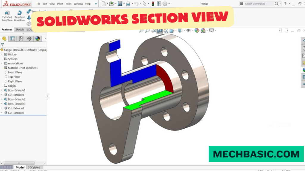
A Section View is a drawing and modeling tool that cuts through a part or assembly to reveal the internal features hidden inside the model. It helps engineers clearly display holes, ribs, slots, and internal components.
How to Create a Section View
- Open the part, assembly, or drawing.
- Click Section View from the View Layout (Drawing) or Heads-Up View toolbar.
- Select the cutting plane or sketch line.
- Choose the section direction and offset if needed.
- Click OK to generate the section view.
Types of Section Views
- Full Section – Cuts completely through the model.
- Half Section – Shows one half in section and the other half externally.
- Offset Section – Uses a bent cutting line to pass through multiple features.
- Broken-out Section – Removes only a local portion to expose internal details.
Applications
Section views are used in mechanical drawings, assemblies, manufacturing documentation, product inspection, and engineering communication to clearly represent internal geometry.
Key Takeaway
Model → Section View → Select Cutting Plane → Set Direction → OK → View Internal Features
In this article:
Section View in SOLIDWORKS
A Section View in SOLIDWORKS is a drawing or model-viewing technique used to reveal the internal features of a 3D part or assembly by virtually cutting through the model.
Instead of displaying only the outside geometry, a section view allows engineers and designers to clearly see internal components such as:
- Holes
- Shafts
- Ribs
- Cavities
- Internal passages
- Bearings
- Gears
- Internal walls
Section views are especially important for engineering drawings, mechanical design, manufacturing, inspection, and assembly documentation.
What is a Section View?
A Section View represents a model as if it has been cut along a defined plane.
The portion of the model in front of the cutting plane is visually removed, allowing the internal geometry to be displayed.
For example, consider a component containing an internal hole.
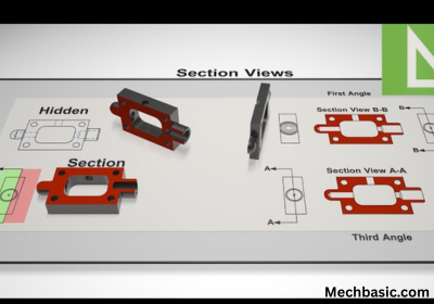
Normal View
You can see the outside of the component, but the internal geometry may be hidden.
Section View
The component is virtually cut, revealing the hole and other internal features.
In engineering drawings, the exposed cut surfaces are typically represented using section hatching.
How to Create a Section View
The exact workflow depends on whether you are creating a section view in a part/assembly model or in a drawing.
Method 1: Section View in a Part or Assembly
Step 1: Open the Model
Open the SOLIDWORKS part or assembly.
Step 2: Activate Section View
Select:
View → Display → Section View
or use the Section View command from the appropriate view tools.
Step 3: Select the Cutting Plane
Choose a reference plane or planar face.
Common options include:
- Front Plane
- Top Plane
- Right Plane
- A model face
- A reference plane
Step 4: Position the Section
Adjust the section plane to determine where the virtual cut occurs.
You can change the cutting location and orientation depending on the section configuration.
Step 5: Confirm the Section
Accept the section view to display the internal geometry.
You can then rotate and inspect the model.
Method 2:Creating a Section View in a Drawing
Section views are particularly important in SOLIDWORKS drawings.
Step 1: Open a Drawing
Create or open a SOLIDWORKS drawing containing a model view.
Step 2: Select the Parent View
Select the drawing view from which you want to create the section.
Step 3: Select Section View
Choose:
Section View
from the drawing-view tools.
Step 4: Draw the Cutting Line
Create a section line through the area you want to inspect.
For example:
A → A
The line indicates the location and direction of the cutting plane.
Step 5: Position the Section View
Move the resulting section view to the desired location on the drawing sheet.
Step 6: Add Dimensions and Annotations
Add relevant:
- Dimensions
- Tolerances
- Notes
- Section labels
The section view can then be used as part of the manufacturing drawing.
Types of Section Views
SOLIDWORKS provides several section-view approaches for different engineering requirements.
1. Full Section View
A Full Section View cuts completely through the component along a section plane.
It is useful for showing the internal structure of a part or assembly.
Applications
- Housings
- Pipes
- Cylindrical components
- Machinery
- Enclosures
2. Half Section View
A Half Section View combines:
- One half of the external view
- One half of the sectional view
It is especially useful for symmetrical components.
Example
A shaft housing can show:
Half exterior + Half interior
This allows both the external shape and internal features to be understood in one view.
3. Offset Section View
An Offset Section View uses a cutting plane that changes direction to pass through multiple important features.
For example, a section line might pass through:
Hole → Shaft → Bearing → Internal cavity
even though these features are not aligned on a single straight line.
This is very useful for complex mechanical components.
4. Aligned Section View
An Aligned Section View allows certain features to be rotated or aligned into the cutting plane.
It is commonly useful for components containing circular or radial features.
Examples include:
- Bolt patterns
- Radial holes
- Cylindrical components
- Flanges
5. Broken-Out Section
A Broken-Out Section removes only a localized portion of the model.
Instead of cutting through the entire component, a small area is removed to expose an internal feature.
Example
A housing may require only a small section to reveal:
- Bearing position
- Internal hole
- Shaft location
This avoids creating a full section view when only one area needs clarification.
6. Section View of an Assembly
Section views can also be used with assemblies to reveal internal components.
For example, an assembly section could show:
Housing → Bearing → Shaft → Gear
This helps engineers understand how components fit together.
Section Hatching
In engineering drawings, cut surfaces are typically represented using hatching.
Hatching helps identify the areas that have been intersected by the cutting plane.
Different components in an assembly may use different hatch orientations or spacing to make the individual parts easier to distinguish.
Applications
1. Mechanical Engineering
Section views are commonly used to display:
- Internal mechanisms
- Shafts
- Bearings
- Gears
- Housings
- Bushings
2. Manufacturing
Manufacturers use section views to understand:
- Internal dimensions
- Wall thickness
- Hole locations
- Cavities
- Machined features
3. Assembly Design
Section views help engineers understand how individual components fit together.
For example:
Bolt → Bracket → Bearing → Shaft → Housing
can be displayed in a single sectional view.
4. Engineering Drawings
Section views improve drawing clarity by eliminating excessive hidden lines.
Instead of displaying many hidden edges, a section view directly exposes the internal geometry.
5. Inspection
Section views can help inspectors understand important internal dimensions and manufacturing features.
Examples include:
- Bore diameter
- Wall thickness
- Internal cavity dimensions
- Hole alignment
6. Product Design
Designers can use section views to verify whether internal components fit correctly within an enclosure or housing.
Section View vs. Standard View
| Feature | Standard View | Section View |
|---|---|---|
| Shows exterior | Yes | Yes |
| Shows internal geometry | Limited | Excellent |
| Hidden lines required | Often | Reduced |
| Internal components | Difficult to interpret | Easy |
| Manufacturing drawings | Useful | Very useful |
| Assembly inspection | Good | Excellent |
Best Practices
1. Choose the Correct Cutting Plane
Position the section so that it clearly passes through the important internal features.
2. Avoid Unnecessary Sections
Use a section view only when it improves the understanding of the design.
3. Use Appropriate Section Types
Choose between:
- Full
- Half
- Offset
- Aligned
- Broken-out
depending on the geometry.
4. Keep Hatching Clear
Ensure hatch patterns do not interfere with dimensions, notes, or other drawing information.
5. Follow Drafting Standards
Use the appropriate company or industry drafting standard for:
- Section lines
- Hatching
- Labels
- Dimensions
- Component representation
6. Check Assembly Components
When creating assembly sections, verify that components are displayed correctly and that standard drafting conventions are followed.
Frequently Asked Questions (FAQs)
1. What is a Section View in SOLIDWORKS?
A Section View virtually cuts through a part or assembly to reveal its internal geometry.
2. Why are section views used?
They make internal features easier to understand and reduce the need for excessive hidden lines in engineering drawings.
3. What are common types of section views?
Common types include Full Section, Half Section, Offset Section, Aligned Section, and Broken-Out Section.
4. Can I create section views in assemblies?
Yes. Section views can be used to inspect internal assembly components and understand how parts fit together.
5. What is a Broken-Out Section?
A Broken-Out Section removes a localized portion of a model to expose a specific internal feature without creating a full section.
6. Are section views important for manufacturing drawings?
Yes. They are extremely useful for communicating internal dimensions, holes, cavities, wall thicknesses, and component relationships to manufacturers and inspectors.
Conclusion
Section View in SOLIDWORKS is an essential tool for understanding and communicating the internal geometry of parts and assemblies.
The typical workflow is:
Select Model/Drawing View → Define Cutting Plane → Create Section → Position View → Add Dimensions & Annotations
The main section-view types include Full, Half, Offset, Aligned, and Broken-Out sections.
By using the appropriate section view and following proper engineering-drawing standards, designers can create clearer documentation, simplify manufacturing interpretation, and make complex internal features much easier to understand.
SOLIDWORKS Design Help: Creating a Section View Manually in Drawings: Step-by-step guide for placing 2D section lines, multi-line offsets, partial sections, and managing drawing view alignments.
Latest articles:

Best Budget Workstation Laptops for SolidWorks and Heavy 3D Assembly Modeling
Best Budget Workstation Laptops for SolidWorks and Heavy 3D Assembly Modeling Overview What Does SOLIDWORKS…

SolidWorks Standard vs Professional vs Premium: Full Feature Comparison
SolidWorks Standard vs Professional vs Premium: Full Feature Comparison Overview: SOLIDWORKS Package Overview SOLIDWORKS comes…

SolidWorks 2026 License Cost: Perpetual vs Subscription Pricing Breakdown
SolidWorks 2026 License Cost: Perpetual vs Subscription Pricing Breakdown Overview: SOLIDWORKS 2026 License Options SOLIDWORKS…

Flatness-GD&T | GD&T Tutorials

ANSI vs ISO Standards-Key Differences you need to know

Straightness-GD&T | GD&T Tutorials
Related Tags:
Categories:




















