
Key Takeaways:
SOLIDWORKS CAM
What is SOLIDWORKS CAM?
SOLIDWORKS CAM is a Computer-Aided Manufacturing (CAM) solution integrated with SOLIDWORKS that converts 3D CAD models into CNC machining operations and toolpaths. It helps engineers and manufacturers move from product design to machining within the same environment.
Key Features of SOLIDWORKS CAM:
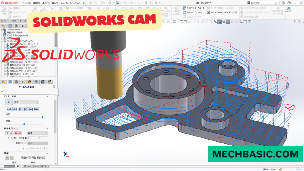
SOLIDWORKS CAM provides tools for 2.5-axis and 3-axis milling, turning, automatic feature recognition, toolpath generation, machining simulation, and CNC G-code generation.
How SOLIDWORKS CAM Works:
The typical workflow is CAD Model → Define Machine & Stock → Recognize Features → Select Tools → Generate Toolpaths → Simulate → Post-Process → CNC Machine.
Applications of SOLIDWORKS CAM:
SOLIDWORKS CAM is commonly used for manufacturing mechanical components, molds, fixtures, automotive parts, aerospace components, and machine-tool parts.
Advantages of SOLIDWORKS CAM:
It reduces programming time, improves machining accuracy, minimizes errors, allows toolpath simulation before machining, and provides a direct connection between CAD design and CNC manufacturing.
Key Takeaway
SOLIDWORKS CAD → SOLIDWORKS CAM → Toolpath → G-Code → CNC Machine → Finished Part
In this article:
- SOLIDWORKS CAM
- What is SOLIDWORKS CAM?
- Key Features of SOLIDWORKS CAM
- How SOLIDWORKS CAM Works
- Applications of SOLIDWORKS CAM
- Advantages of SOLIDWORKS CAM
- SOLIDWORKS CAM vs. Traditional CAD-to-CAM Workflow
- Skills Required for SOLIDWORKS CAM
- Advantages for a Manufacturing Career
- Frequently Asked Questions (FAQs)
- Conclusion
SOLIDWORKS CAM
SOLIDWORKS CAM is a computer-aided manufacturing (CAM) solution that integrates design and CNC manufacturing within the SOLIDWORKS environment. It uses the SOLIDWORKS 3D model to create CNC toolpaths and manufacturing operations for machining parts.
By connecting CAD and CAM in the same environment, engineers and CNC programmers can reduce data-transfer problems, update manufacturing operations when the design changes, and create machining strategies directly from the digital model.
What is SOLIDWORKS CAM?
SOLIDWORKS CAM is a CAM solution based on CAMWorks technology that works within the SOLIDWORKS environment.
It allows users to:
- Import or create 3D CAD models
- Define manufacturing setups
- Select machining operations
- Generate CNC toolpaths
- Simulate machining
- Post-process toolpaths into machine-specific G-code
Key Features of SOLIDWORKS CAM
1. Integrated CAD/CAM Workflow
One of the biggest advantages of SOLIDWORKS CAM is that it works directly with the SOLIDWORKS design environment.
This allows designers and manufacturers to work from the same model.
2. Feature Recognition
SOLIDWORKS CAM can recognize machinable features such as:
- Holes
- Pockets
- Slots
- Bosses
- Faces
- Contours
This can reduce the amount of manual programming required.
3. 2.5-Axis Milling
SOLIDWORKS CAM can be used for common milling operations such as:
- Facing
- Pocketing
- Contouring
- Drilling
- Slotting
These operations are widely used in CNC machining.
4. 3-Axis Milling
For more complex components, 3-axis machining strategies can be used to machine contoured surfaces and complex geometries.
Applications include:
- Molds
- Dies
- Mechanical components
- Prototypes
- Complex surfaces
5. Turning
Depending on the SOLIDWORKS CAM configuration and license, CNC turning workflows can be used for rotational components.
Typical applications include:
- Shafts
- Bushings
- Pins
- Cylindrical components
6. Automatic Toolpath Generation
SOLIDWORKS CAM can automatically generate machining operations based on recognized features and selected machining strategies.
This can make programming repetitive parts faster.
7. Toolpath Simulation
Before sending a program to a CNC machine, users can simulate the machining process.
Simulation can help identify:
- Tool collisions
- Incorrect cutting operations
- Remaining material
- Machining sequence problems
- Potential setup issues
This reduces the risk of discovering problems during actual machining.
8. Associativity with SOLIDWORKS Models
Because SOLIDWORKS CAM works with the CAD model, design changes can be reflected in manufacturing operations more efficiently than workflows that rely on disconnected CAD and CAM files.
How SOLIDWORKS CAM Works
A typical SOLIDWORKS CAM workflow consists of several stages.
Step 1: Create the SOLIDWORKS Model
First, create or open the component in SOLIDWORKS.
For example:
Bracket → 3D Part Model
Step 2: Define the Machine
Select the appropriate machine configuration.
Depending on the available SOLIDWORKS CAM functionality, this may include:
- Milling
- Turning
- Multi-axis machining
Step 3: Define the Stock
Specify the raw material from which the component will be manufactured.
For example:
Finished Part: 100 × 60 × 20 mm
Raw Stock: 105 × 65 × 25 mm
The additional material represents machining allowance.
Step 4: Define the Coordinate System
Set the machining coordinate system and establish the appropriate:
- X-axis
- Y-axis
- Z-axis
- Zero/reference location
Correct setup orientation is essential for CNC machining.
Step 5: Recognize Machinable Features
SOLIDWORKS CAM can analyze the model and identify features such as:
- Holes
- Pockets
- Slots
- Planar faces
- Contours
Step 6: Select Machining Strategies
Choose suitable machining operations.
For example:
Face Milling
↓
Roughing
↓
Pocket Milling
↓
Drilling
↓
Finishing
Step 7: Generate Toolpaths
SOLIDWORKS CAM generates the toolpaths that define how the cutting tool moves through the material.
Step 8: Simulate the Machining Process
Simulate the toolpaths to verify:
- Tool movement
- Material removal
- Collision risks
- Remaining stock
- Machining sequence
Step 9: Post Process
After verification, the toolpaths are converted into CNC machine instructions using the appropriate post processor.
The resulting NC/G-code program can then be transferred to the CNC machine according to the machine tool’s workflow and controls.
Applications of SOLIDWORKS CAM
1. CNC Milling
SOLIDWORKS CAM is commonly used for machining:
- Brackets
- Plates
- Housings
- Fixtures
- Machine components
2. CNC Turning
For suitable configurations, it can support machining of:
- Shafts
- Pins
- Bushings
- Cylindrical components
3. Prototyping
SOLIDWORKS CAM is useful for rapidly converting a CAD design into a machined prototype.
Typical workflow:
Design → CAM → CNC → Prototype
4. Machine Component Manufacturing
Applications include:
- Gears and related components
- Bearing housings
- Machine brackets
- Fixtures
- Mechanical components
5. Tool and Fixture Manufacturing
SOLIDWORKS CAM can support the manufacture of:
- Jigs
- Fixtures
- Tooling components
- Production aids
6. Product Development
Design engineers can use an integrated CAD/CAM workflow to evaluate how a component will actually be manufactured.
This encourages design for manufacturability (DFM) during product development.
Advantages of SOLIDWORKS CAM
1. CAD and CAM Integration
The biggest advantage is the close relationship between the SOLIDWORKS model and CAM operations.
2. Reduces Data Translation
Traditional workflows may require transferring CAD data between separate applications.
SOLIDWORKS CAM can reduce this separation by working within the SOLIDWORKS environment.
3. Faster Programming
Feature recognition and automatic machining strategies can reduce repetitive programming work.
4. Easier Design Changes
When the SOLIDWORKS design changes, associated manufacturing information can be updated more efficiently.
5. Toolpath Simulation
Simulation provides an opportunity to detect machining problems before running the program on an actual CNC machine.
6. Improved Design for Manufacturing
Engineers can consider machining requirements during the design process instead of waiting until manufacturing programming begins.
7. Single Engineering Environment
Designers and manufacturing engineers can work around the same CAD model and manufacturing workflow.
SOLIDWORKS CAM vs. Traditional CAD-to-CAM Workflow
Traditional Workflow
CAD Software
↓
Export Model
↓
Import into CAM Software
↓
Repair/Prepare Geometry
↓
Create Toolpaths
↓
Post Process
This can introduce additional data-management and translation steps.
SOLIDWORKS CAM Workflow
SOLIDWORKS CAD
↓
SOLIDWORKS CAM
↓
Feature Recognition
↓
Toolpaths
↓
Simulation
↓
Post Process
The integrated approach can simplify the workflow, particularly when designs are frequently revised.
Skills Required for SOLIDWORKS CAM
Learning the software is only one part of becoming a good CAM engineer.
You should also understand:
- CNC machining
- Cutting tools
- Feeds and speeds
- Workholding
- Coordinate systems
- Machine axes
- Machining operations
- Materials
- Tolerances
- Surface finish
- G-code fundamentals
- Design for manufacturability
Important
A CAM software tool can generate toolpaths, but engineering judgment is still required to determine whether a machining process is safe, efficient, and suitable for the actual machine and tooling.
Advantages for a Manufacturing Career
Learning SOLIDWORKS + SOLIDWORKS CAM can give you a broader skill set:
CAD
→ Design the component
CAM
→ Create the machining strategy
CNC
→ Manufacture the component
This combination is particularly useful for people pursuing CAD/CAM, manufacturing engineering, CNC programming, and mechanical design careers.
Frequently Asked Questions (FAQs)
1. What is SOLIDWORKS CAM used for?
SOLIDWORKS CAM is used to create CNC machining toolpaths from SOLIDWORKS models and prepare those toolpaths for manufacturing.
2. Is SOLIDWORKS CAM the same as SOLIDWORKS?
No. SOLIDWORKS is primarily the CAD/design environment, while SOLIDWORKS CAM provides computer-aided manufacturing and CNC programming capabilities.
3. Can SOLIDWORKS CAM create G-code?
Yes. After generating and verifying toolpaths, a suitable post processor can convert them into machine-specific CNC code.
4. Can SOLIDWORKS CAM be used for CNC milling?
Yes. Milling is a major application, including common operations such as facing, pocketing, contouring, drilling, roughing, and finishing.
5. Is SOLIDWORKS CAM good for beginners?
Yes, especially for someone who already understands basic SOLIDWORKS modeling. However, learning CNC machining fundamentals is just as important as learning the software.
6. Is SOLIDWORKS CAM useful for getting a job?
Yes. SOLIDWORKS + CAM + CNC knowledge can strengthen your profile for CAD/CAM and manufacturing-related positions.
Conclusion
SOLIDWORKS CAM connects 3D CAD design with CNC manufacturing, allowing engineers and programmers to create machining operations directly from SOLIDWORKS models.
Its major capabilities include feature recognition, milling, turning, toolpath generation, machining simulation, and post processing.
For students and mechanical engineers, learning SOLIDWORKS + SOLIDWORKS CAM + CNC fundamentals can provide a strong foundation for careers in mechanical design, manufacturing engineering, CAD/CAM, CNC programming, and product development.
SOLIDWORKS CAM Official Page: Comprehensive breakdown of standard vs. professional capabilities, rules-based machining, turning, and 2.5- to 5-axis milling.
Latest articles:
Best Budget Workstation Laptops for SolidWorks and Heavy 3D Assembly Modeling
Best Budget Workstation Laptops for SolidWorks and Heavy 3D Assembly Modeling Overview What Does SOLIDWORKS…

SolidWorks Standard vs Professional vs Premium: Full Feature Comparison
SolidWorks Standard vs Professional vs Premium: Full Feature Comparison Overview: SOLIDWORKS Package Overview SOLIDWORKS comes…

SolidWorks 2026 License Cost: Perpetual vs Subscription Pricing Breakdown
SolidWorks 2026 License Cost: Perpetual vs Subscription Pricing Breakdown Overview: SOLIDWORKS 2026 License Options SOLIDWORKS…

Flatness-GD&T | GD&T Tutorials

ANSI vs ISO Standards-Key Differences you need to know

Straightness-GD&T | GD&T Tutorials
Related Tags:
Categories:




















