
Key Takeaways:
What is SolidWorks FEA?
SolidWorks FEA (Finite Element Analysis) is a simulation tool integrated within SolidWorks that helps engineers analyze the strength, durability, and performance of parts and assemblies under real-world conditions. It enables virtual testing before manufacturing, reducing design errors, cost, and development time.
Features of SolidWorks FEA:
SolidWorks FEA provides tools for static stress analysis, thermal analysis, frequency (modal) analysis, buckling analysis, fatigue analysis, drop test simulation, and motion analysis. It also supports easy meshing, result visualization, and design optimization.
Applications of SolidWorks FEA:
SolidWorks FEA is widely used in the automotive, aerospace, mechanical, consumer products, industrial equipment, and manufacturing industries to validate product designs, optimize components, and improve safety and reliability.
Advantages of SolidWorks FEA:
SolidWorks FEA reduces the need for physical prototypes, identifies design weaknesses early, improves product quality, shortens development time, lowers manufacturing costs, and integrates seamlessly with the SolidWorks CAD environment.
Types of Analysis in SolidWorks FEA:
- Static Analysis – Evaluates stress, strain, and displacement under constant loads.
- Thermal Analysis – Studies heat transfer and temperature distribution.
- Frequency (Modal) Analysis – Determines natural frequencies and mode shapes.
- Buckling Analysis – Predicts structural instability under compressive loads.
- Fatigue Analysis – Estimates component life under repeated loading.
- Drop Test Analysis – Simulates the impact of accidental drops.
- Motion Analysis – Evaluates movement, forces, and interactions in mechanical assemblies.
In this article:
- What is SolidWorks FEA?
- SolidWorks FEA (Finite Element Analysis)
- What is SolidWorks FEA?
- Features of SolidWorks FEA
- Types of Analysis in SolidWorks FEA
- Applications of SolidWorks FEA
- Advantages of SolidWorks FEA
- Comparison of SolidWorks FEA with Traditional Testing
- Best Practices for Using SolidWorks FEA
- Summary Table
- Frequently Asked Questions (FAQs)
- Conclusion
SolidWorks FEA (Finite Element Analysis)
Introduction
SolidWorks FEA is the simulation and analysis capability available within SolidWorks Simulation, an integrated module of the SolidWorks CAD software developed by Dassault Systèmes. It enables engineers and designers to evaluate the structural, thermal, dynamic, and fatigue performance of components and assemblies before manufacturing.
Using the Finite Element Method (FEM), SolidWorks FEA divides a CAD model into small finite elements, applies loads and boundary conditions, and calculates how the model behaves under real-world operating conditions. This helps identify design weaknesses, optimize products, reduce material usage, and minimize the need for costly physical prototypes.
SolidWorks FEA is widely used in mechanical engineering, automotive, aerospace, industrial machinery, consumer products, and manufacturing because of its ease of use and seamless integration with SolidWorks CAD.
What is SolidWorks FEA?
SolidWorks FEA is a computer-aided engineering (CAE) tool integrated into SolidWorks that allows users to simulate the physical behavior of parts and assemblies under different loading conditions. Engineers can predict stress, strain, displacement, temperature distribution, vibration, and fatigue life without building a physical prototype.
Unlike standalone simulation software, SolidWorks FEA works directly with SolidWorks models, allowing design changes to be analyzed quickly without exporting geometry.
SolidWorks FEA helps engineers:
- Validate designs before manufacturing
- Detect high-stress regions
- Optimize product weight
- Improve durability
- Increase safety
- Reduce product development time
- Lower manufacturing costs
Features of SolidWorks FEA
SolidWorks FEA provides a wide range of simulation capabilities.
1. CAD Integration
SolidWorks Simulation is fully integrated with SolidWorks CAD.
Benefits
- No need to export models
- Faster design modifications
- Automatic geometry updates
- Simplified workflow
2. Automatic Mesh Generation
The software automatically creates finite element meshes for analysis.
Features
- Automatic meshing
- Manual mesh refinement
- Adaptive mesh refinement
- High-quality mesh generation
3. Material Library
SolidWorks includes an extensive database of engineering materials.
Examples include:
- Steel
- Aluminum
- Copper
- Titanium
- Plastics
- Rubber
- Composite materials
Users can also create custom material properties.
4. Assembly Analysis
Engineers can analyze complete assemblies instead of individual parts.
Simulation includes:
- Contacts
- Bolted joints
- Bearings
- Springs
- Welds
- Connectors
5. Result Visualization
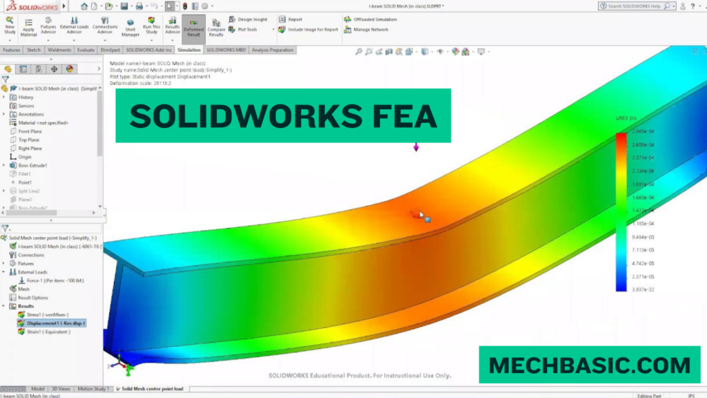
Simulation results are displayed using colorful contour plots and animations.
Typical outputs include:
- Von Mises stress
- Principal stress
- Displacement
- Strain
- Temperature distribution
- Factor of Safety
- Deformed shape
6. Design Optimization
SolidWorks helps engineers optimize:
- Weight
- Material usage
- Geometry
- Strength
- Performance
7. Report Generation
The software automatically generates professional reports containing:
- Model information
- Material properties
- Loads
- Boundary conditions
- Mesh details
- Graphs
- Simulation results
8. Parametric Studies
Engineers can evaluate multiple design variations by changing dimensions, materials, or loads to identify the best-performing design.
Types of Analysis in SolidWorks FEA
SolidWorks Simulation supports several types of engineering analyses.
1. Static Analysis
Determines how a component behaves under constant loads.
Results
- Stress
- Strain
- Deformation
- Factor of Safety
Applications
- Brackets
- Machine frames
- Pressure vessels
- Shafts
2. Thermal Analysis
Evaluates heat transfer and temperature distribution.
Applications
- Heat exchangers
- Electronic components
- Engine parts
- Cooling systems
3. Frequency (Modal) Analysis
Calculates the natural frequencies and mode shapes of components.
Applications
- Rotating machinery
- Machine tools
- Vehicle components
4. Buckling Analysis
Determines the critical load at which a structure becomes unstable.
Applications
- Columns
- Frames
- Thin-walled structures
5. Fatigue Analysis
Predicts the service life of components subjected to repeated loading.
Applications
- Springs
- Gears
- Crankshafts
- Connecting rods
6. Drop Test Analysis
Simulates the impact of a product being dropped from a specified height.
Applications
- Mobile devices
- Consumer electronics
- Packaging design
7. Pressure Vessel Analysis
Evaluates stresses and deformations in tanks and pressure vessels subjected to internal or external pressure.
8. Motion Analysis
Studies the movement of mechanisms and calculates forces generated during operation.
Applications
- Linkages
- Gear trains
- Cam mechanisms
- Robotic arms
9. Nonlinear Analysis (available in advanced simulation packages)
Handles:
- Large deformations
- Plastic deformation
- Contact problems
- Hyperelastic materials
Applications of SolidWorks FEA
SolidWorks FEA is used in many engineering fields.
Mechanical Engineering
- Shafts
- Bearings
- Gears
- Machine frames
- Springs
- Pressure vessels
Automotive Engineering
- Suspension components
- Brake systems
- Engine brackets
- Chassis
- Steering components
Aerospace Engineering
- Aircraft brackets
- Wing structures
- Landing gear components
- Engine mounts
Manufacturing
- Tooling
- Fixtures
- Jigs
- Machine parts
- Production equipment
Consumer Products
- Household appliances
- Furniture
- Sports equipment
- Electronic enclosures
Industrial Equipment
- Pumps
- Compressors
- Conveyors
- Cranes
- Material handling systems
Medical Devices
- Prosthetic components
- Surgical instruments
- Orthopedic implants
Educational and Research Institutions
- Engineering education
- Research projects
- Product development studies
Advantages of SolidWorks FEA
1. Fully Integrated with SolidWorks
No file conversion is required, reducing errors and saving time.
2. Easy to Learn
Its user-friendly interface makes it suitable for beginners while still offering advanced capabilities for professionals.
3. Faster Product Development
Virtual testing enables rapid design iterations and quicker decision-making.
4. Reduces Prototype Costs
Many design issues can be identified through simulation, reducing the need for physical prototypes.
5. Improves Product Quality
Weak points, excessive stresses, and deformation can be detected before manufacturing.
6. Enhances Safety
Engineers can evaluate failure risks and improve product reliability.
7. Supports Multiple Analysis Types
A single environment can perform structural, thermal, fatigue, buckling, and motion analyses.
8. Optimizes Material Usage
Designs can be made lighter and more efficient without compromising strength.
9. Professional Reporting
Automatically generates detailed simulation reports suitable for documentation and presentations.
10. Better Collaboration
Designers and analysts can work on the same CAD model, improving communication and reducing design errors.
Comparison of SolidWorks FEA with Traditional Testing
| Feature | SolidWorks FEA | Physical Testing |
|---|---|---|
| Cost | Lower | Higher |
| Time | Faster | Slower |
| Design Changes | Easy | Difficult |
| Prototype Requirement | Minimal | Essential |
| Repeatability | High | Moderate |
| Visualization | Excellent | Limited |
| Early Error Detection | Yes | Often after prototype |
Best Practices for Using SolidWorks FEA
- Use accurate material properties.
- Apply realistic loads and boundary conditions.
- Create a high-quality mesh.
- Refine the mesh in high-stress areas.
- Validate simulation results with experiments or analytical calculations.
- Check contact definitions in assemblies.
- Review stress concentrations carefully.
- Perform mesh convergence studies for critical designs.
Summary Table
| Aspect | Description |
|---|---|
| Software | SolidWorks Simulation |
| Developer | Dassault Systèmes |
| Purpose | Simulate and analyze engineering designs |
| Integration | Fully integrated with SolidWorks CAD |
| Common Analyses | Static, Thermal, Fatigue, Buckling, Modal, Motion |
| Main Users | Mechanical, automotive, aerospace, manufacturing engineers |
Frequently Asked Questions (FAQs)
1. What is SolidWorks FEA?
SolidWorks FEA is the simulation module within SolidWorks that uses the Finite Element Method (FEM) to analyze the structural, thermal, and dynamic behavior of parts and assemblies.
2. What is the difference between SolidWorks and SolidWorks Simulation?
SolidWorks is a CAD software used to create 3D models and drawings, while SolidWorks Simulation is an integrated FEA tool used to analyze those models under various operating conditions.
3. What types of analyses can SolidWorks FEA perform?
It supports static, thermal, frequency (modal), buckling, fatigue, pressure vessel, motion, drop test, and certain nonlinear analyses (depending on the license).
4. Which industries use SolidWorks FEA?
It is widely used in mechanical, automotive, aerospace, manufacturing, consumer products, medical devices, and industrial equipment design.
5. Does SolidWorks FEA require a separate CAD model?
No. It works directly with SolidWorks CAD models, allowing seamless design updates and simulations.
6. What are the advantages of using SolidWorks FEA?
It reduces development costs, speeds up product design, improves product quality, minimizes prototype testing, optimizes materials, and provides detailed simulation reports.
7. Can SolidWorks FEA analyze assemblies?
Yes. It can analyze complete assemblies, including contacts, bolts, welds, bearings, springs, and other connectors.
8. Is SolidWorks FEA suitable for beginners?
Yes. Its intuitive interface and integration with SolidWorks CAD make it suitable for students, beginners, and experienced engineers.
9. Can SolidWorks FEA replace physical testing?
No. It significantly reduces the number of prototypes required, but physical testing is still recommended to validate simulation results, especially for critical or safety-related applications.
10. What factors affect the accuracy of SolidWorks FEA results?
Accuracy depends on proper material properties, mesh quality, realistic boundary conditions, correct load application, and validation against experimental or analytical results.
Conclusion
SolidWorks FEA is a powerful and user-friendly simulation solution that enables engineers to evaluate and optimize designs before manufacturing. By integrating directly with SolidWorks CAD, it streamlines the design and analysis process, allowing rapid testing of structural, thermal, fatigue, and dynamic performance. Its wide range of analysis tools, automatic meshing, comprehensive material libraries, and professional reporting capabilities make it an essential tool for product development across industries. By using SolidWorks FEA effectively, engineers can reduce costs, improve product reliability, shorten development cycles, and create safer, higher-quality engineering designs.
Official Training Guides: Access beginner tutorials and video demonstrations via the SOLIDWORKS Simulation Training Portal.
Latest articles:

Best Budget Workstation Laptops for SolidWorks and Heavy 3D Assembly Modeling
Best Budget Workstation Laptops for SolidWorks and Heavy 3D Assembly Modeling Overview What Does SOLIDWORKS…

SolidWorks Standard vs Professional vs Premium: Full Feature Comparison
SolidWorks Standard vs Professional vs Premium: Full Feature Comparison Overview: SOLIDWORKS Package Overview SOLIDWORKS comes…

SolidWorks 2026 License Cost: Perpetual vs Subscription Pricing Breakdown
SolidWorks 2026 License Cost: Perpetual vs Subscription Pricing Breakdown Overview: SOLIDWORKS 2026 License Options SOLIDWORKS…

Flatness-GD&T | GD&T Tutorials

ANSI vs ISO Standards-Key Differences you need to know

Straightness-GD&T | GD&T Tutorials
Categories:




















