
Key Takeaways:
Basic Fundamentals of Drafting
What is Drafting?
Drafting is the process of creating accurate technical drawings that communicate the shape, size, materials, and manufacturing or construction requirements of a design.
1. Drawing Lines
Different line types communicate different information:
- Object lines – Visible edges
- Hidden lines – Invisible features
- Center lines – Centers and axes
- Dimension lines – Measurements
- Construction lines – Used for layout and reference
2. Geometric Shapes
Basic geometry forms the foundation of technical drawings:
Lines → Circles → Arcs → Polygons → Curves
3. Orthographic Projection
Represents a 3D object using multiple 2D views:
Front View → Top View → Side View
4. Isometric Drawing
Shows a 3D representation of an object on a 2D drawing sheet, typically using 30° isometric axes.
5. Dimensions
Dimensions communicate the exact size and location of features, including:
- Length
- Diameter
- Radius
- Angle
- Hole location
6. Scale
Scale defines the relationship between the drawing size and the actual object.
Examples: 1:1, 1:2, 2:1, 1:10
7. Sections
Section views expose internal features that cannot be clearly shown in normal exterior views.
8. Tolerances
Tolerances specify the acceptable variation from the nominal dimension.
Example: 50 ± 0.05 mm
9. Symbols & Annotations
Drafting uses standardized symbols for surface finish, welding, GD&T, materials, threads, and other manufacturing requirements.
10. Drawing Standards
Technical drawings follow standards such as ISO, ASME, ANSI, and BIS to maintain consistency and make drawings understandable across organizations.
Key Takeaway
Geometry → Lines → Views → Dimensions → Scale → Sections → Tolerances → Symbols → Standards
These fundamentals are the foundation for becoming a skilled CAD Draftsman or Design Engineer.
In this article:
Basic Fundamentals of Drafting
Drafting fundamentals are the basic principles used to create, read, and interpret technical drawings. Whether you work in mechanical, civil, architectural, electrical, structural, piping, or HVAC drafting, understanding these fundamentals is essential before moving on to advanced CAD software.
Modern CAD programs automate many drafting tasks, but the underlying principles of lines, geometry, projection, dimensions, scale, sections, tolerances, symbols, and standards remain fundamental.
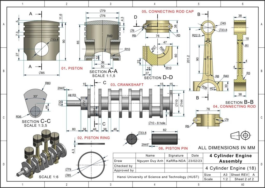
1. Drawing Lines
Lines are the basic building blocks of a technical drawing. Different line types communicate different information.
Common Line Types
- Object/visible lines – Show visible edges and outlines.
- Hidden lines – Represent features that cannot be directly seen.
- Center lines – Indicate centers, axes, and symmetrical features.
- Dimension lines – Show the distance being measured.
- Extension lines – Extend from an object to indicate where a dimension applies.
- Construction lines – Assist with creating geometry.
- Section lines – Indicate surfaces exposed by a section cut.
Using the correct line type makes drawings easier to understand and interpret.
2. Geometric Shapes
Technical drawings are created from basic geometric elements.
Common Geometry
- Lines
- Circles
- Arcs
- Polygons
- Rectangles
- Ellipses
- Curves
In CAD software, these basic elements can be combined to create complex components and structures.
3. Orthographic Projection
Orthographic projection represents a three-dimensional object using multiple two-dimensional views.
Common views include:
- Front view
- Top view
- Right-side view
- Left-side view
- Bottom view
Orthographic projection is widely used in mechanical, manufacturing, architectural, and engineering drawings.
Projection Systems
Two commonly encountered systems are:
- First-angle projection
- Third-angle projection
The appropriate projection method should be clearly identified according to the applicable drafting standard.
4. Isometric Drawing
An isometric drawing provides a three-dimensional representation of an object on a two-dimensional sheet.
The three principal directions are typically represented at approximately 120° from one another.
Isometric drawings are useful for:
- Visualizing components
- Assembly documentation
- Installation drawings
- Piping layouts
- Technical presentations
Unlike an orthographic drawing, an isometric view allows the viewer to understand the object’s 3D form more quickly.
5. Dimensions
Dimensions communicate the size and location of features.
Common dimensions include:
- Length
- Width
- Height
- Diameter
- Radius
- Angle
- Depth
- Hole location
Good dimensioning should provide enough information to manufacture or construct the design without unnecessary or confusing dimensions.
6. Scale
Scale represents the relationship between the size of the drawing and the actual object.
Common Scales
- 1:1 — Full size
- 1:2 — Half size
- 2:1 — Twice the actual size
- 1:10 — One-tenth of actual size
- 10:1 — Ten times actual size
Example
At a 1:2 scale, a 100 mm object is represented as 50 mm on the drawing.
Scale is particularly useful when the actual object is too large or too small to fit conveniently on the drawing sheet.
Important: Dimensions normally state the actual design size; do not assume you should measure the printed drawing to determine a feature’s size.
7. Sections
A section view shows the internal features of an object by imagining that it has been cut through.
Section views make it easier to represent:
- Internal holes
- Cavities
- Ribs
- Passages
- Internal components
- Wall thicknesses
Common Section Types
- Full section
- Half section
- Offset section
- Broken-out section
- Revolved section
- Removed section
Section Lines
The cut surfaces are commonly represented using hatching or section lining according to the applicable drafting standard.
8. Tolerances
Manufacturing processes cannot produce every dimension with absolute mathematical precision.
Tolerances define the acceptable variation from a specified dimension.
Example
50 ± 0.05 mm
The acceptable range is:
49.95 mm to 50.05 mm
Tolerances are important for:
- Manufacturing
- Assembly
- Interchangeability
- Quality control
- Inspection
For mechanical engineering, GD&T (Geometric Dimensioning and Tolerancing) provides a more comprehensive method of controlling geometric requirements.
9. Symbols & Annotations
Technical drawings use standardized symbols and annotations to communicate information efficiently.
Common Examples
- Diameter symbol Ø
- Radius symbol R
- Center marks
- Welding symbols
- Surface-finish symbols
- Datum symbols
- Geometric-tolerance symbols
- Material notes
- General notes
Annotations can also provide information about:
- Materials
- Manufacturing processes
- Surface finishes
- Heat treatment
- Welding
- Inspection requirements
Using recognized symbols reduces ambiguity and makes drawings easier to interpret.
10. Drawing Standards
Drawing standards establish consistent rules for creating and interpreting technical drawings.
Common standards organizations include:
- ISO
- ASME
- ANSI
- DIN
- BS
- JIS
Standards can define conventions for:
- Line types
- Dimensioning
- Projection
- Symbols
- Tolerances
- Drawing layouts
- Lettering
- Section views
The correct standard depends on the industry, company, project, and applicable requirements.
Why Drafting Fundamentals Are Important ?
Learning these fundamentals before becoming highly dependent on CAD tools is important because CAD software mainly provides the tools; the drafter must understand what the drawing needs to communicate.
A strong drafting foundation helps you:
- Create accurate drawings
- Read engineering drawings
- Understand manufacturing requirements
- Communicate designs clearly
- Avoid costly drawing errors
- Work with different CAD platforms
- Follow industry standards
Also Read: What is Technical drawing(Wikipedia)?
Frequently Asked Questions (FAQs)
1. What are the basic fundamentals of drafting?
The basic fundamentals include lines, geometric shapes, orthographic projection, isometric drawing, dimensions, scale, sections, tolerances, symbols and annotations, and drawing standards.
2. Is drafting knowledge necessary for learning AutoCAD?
Yes. Learning drafting fundamentals makes AutoCAD much easier to use effectively because you understand what different lines, dimensions, views, and symbols mean.
3. What is the difference between orthographic and isometric drawing?
Orthographic drawing uses separate 2D views to accurately describe an object, while an isometric drawing provides a 3D-like representation that helps visualize the object’s overall shape.
4. Why are dimensions important in drafting?
Dimensions communicate the required size and location of features, allowing a component or structure to be manufactured or constructed correctly.
5. What is a section view?
A section view represents an object as though it has been cut through, allowing its internal features to be shown clearly.
6. What is tolerance in drafting?
Tolerance specifies the permitted variation from a nominal dimension or geometric requirement.
7. What is the purpose of drawing standards?
Drawing standards provide consistent rules for symbols, dimensions, line types, projections, tolerances, and other technical-documentation practices.
8. What should I learn first for a drafting career?
A good starting sequence is:
Technical Drawing → Geometry → Projection → Dimensioning → Sections → Tolerances → Standards → AutoCAD → 3D CAD
Then specialize according to your target department.
9. Are drafting fundamentals the same for every industry?
The basic principles are similar, but the standards, symbols, drawing conventions, and technical requirements can differ between mechanical, civil, architectural, electrical, structural, piping, and other disciplines.
10. Can I become a good draftsman by learning only CAD software?
CAD software is important, but software knowledge alone is not enough. A good draftsman also needs technical drawing knowledge, industry standards, accuracy, drawing interpretation skills, and an understanding of the relevant engineering or construction field.
Conclusion
Drafting fundamentals provide the foundation for creating and interpreting professional technical drawings. The essential topics include drawing lines, geometric shapes, orthographic projection, isometric drawing, dimensions, scale, sections, tolerances, symbols and annotations, and drawing standards.
Once these fundamentals are understood, learning software such as AutoCAD, SOLIDWORKS, Revit, CATIA, Creo, Civil 3D, or other CAD platforms becomes much more meaningful.
For a drafting career, the ideal approach is:
Drafting Fundamentals → CAD Software → Industry-Specific Skills → Standards → Practical Projects
This combination can prepare you for opportunities across mechanical, civil, architectural, structural, electrical, piping, HVAC, and other drafting departments.
Latest articles:

Best Budget Workstation Laptops for SolidWorks and Heavy 3D Assembly Modeling
Best Budget Workstation Laptops for SolidWorks and Heavy 3D Assembly Modeling Overview What Does SOLIDWORKS…

SolidWorks Standard vs Professional vs Premium: Full Feature Comparison
SolidWorks Standard vs Professional vs Premium: Full Feature Comparison Overview: SOLIDWORKS Package Overview SOLIDWORKS comes…

SolidWorks 2026 License Cost: Perpetual vs Subscription Pricing Breakdown
SolidWorks 2026 License Cost: Perpetual vs Subscription Pricing Breakdown Overview: SOLIDWORKS 2026 License Options SOLIDWORKS…

Flatness-GD&T | GD&T Tutorials

ANSI vs ISO Standards-Key Differences you need to know

Straightness-GD&T | GD&T Tutorials
Related Tags:
Categories:




















