
Key Takeaways:
What is CFD Analysis?
Computational Fluid Dynamics (CFD) is a computer-based simulation technique used to analyze the behavior of fluids (liquids and gases) and their interaction with solid surfaces. It helps engineers predict flow patterns, pressure, temperature, heat transfer, and turbulence before physical testing.
Advantages of CFD Analysis:
CFD reduces the need for physical prototypes, improves design accuracy, identifies performance issues early, optimizes fluid flow, lowers development costs, and shortens product development time.
Applications of CFD Analysis:
CFD is widely used in the automotive, aerospace, mechanical, civil, chemical, energy, HVAC, marine, and biomedical industries for aerodynamic analysis, cooling system design, combustion analysis, ventilation studies, and fluid flow optimization.
How CFD Works:
CFD divides the fluid domain into a mesh of small cells. The governing equations of fluid flow (continuity, momentum, and energy equations) are solved numerically to predict velocity, pressure, temperature, and turbulence throughout the model.
Common CFD Software:
Popular CFD software includes ANSYS Fluent, ANSYS CFX, STAR-CCM+, OpenFOAM, COMSOL Multiphysics, Autodesk CFD, SolidWorks Flow Simulation, and SimScale.
Features of CFD Analysis:
CFD provides tools for fluid flow analysis, heat transfer, turbulence modeling, multiphase flow, combustion simulation, aerodynamic analysis, pressure distribution, and thermal management, enabling engineers to design more efficient and reliable products.
In this article:
CFD Analysis (Computational Fluid Dynamics)
Introduction
Computational Fluid Dynamics (CFD) is a numerical simulation technique used to analyze the behavior of fluids (liquids and gases) and their interaction with solid surfaces. Using advanced mathematical models and computer algorithms, CFD predicts fluid flow, heat transfer, pressure distribution, turbulence, and other physical phenomena without the need for extensive physical testing.
CFD is based on the principles of fluid mechanics, thermodynamics, and numerical methods. Engineers use CFD software to solve complex engineering problems, optimize designs, improve efficiency, reduce development costs, and enhance product performance. Today, CFD is widely used in mechanical, aerospace, automotive, civil, marine, biomedical, chemical, and energy engineering.
What is CFD Analysis?
Computational Fluid Dynamics (CFD) Analysis is the process of using specialized computer software to simulate and study the movement of fluids and the transfer of heat under various operating conditions. Instead of relying solely on experimental testing, CFD creates a virtual model of a system and predicts how fluids behave using numerical solutions of governing equations.
CFD enables engineers to visualize flow patterns and evaluate the performance of products such as aircraft, automobiles, turbines, pumps, HVAC systems, and heat exchangers before they are manufactured.
CFD Analysis helps engineers evaluate:
- Fluid flow behavior
- Pressure distribution
- Velocity distribution
- Temperature distribution
- Heat transfer
- Turbulence
- Drag and lift forces
- Flow separation
- Mixing of fluids
- Combustion processes
How CFD Works
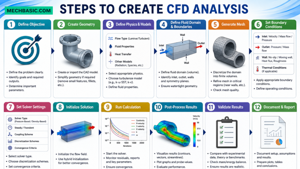
CFD follows a systematic workflow to simulate fluid behavior accurately.
Step 1: Create the Geometry
A 2D or 3D CAD model of the component or system is created using CAD software.
Common CAD software includes:
- SolidWorks
- AutoCAD
- CATIA
- Siemens NX
- Creo
- Fusion 360
Examples of CFD models:
- Pipe systems
- Aircraft wings
- Car bodies
- Pumps
- Heat exchangers
- Wind turbines
Step 2: Define the Fluid Domain
The fluid domain represents the space occupied by the flowing fluid.
Examples include:
- Air around a vehicle
- Water inside a pipeline
- Airflow inside an HVAC duct
- Coolant inside an engine
Step 3: Generate the Mesh
The fluid domain is divided into thousands or millions of small computational cells known as the mesh.
Common Mesh Types
- Structured mesh
- Unstructured mesh
- Hexahedral mesh
- Tetrahedral mesh
- Polyhedral mesh
- Prism layers (boundary layer mesh)
A finer mesh generally improves solution accuracy but increases computational time.
Step 4: Assign Material Properties
Specify the properties of the working fluid.
Typical properties include:
- Density
- Dynamic viscosity
- Thermal conductivity
- Specific heat capacity
- Compressibility
Step 5: Apply Boundary Conditions
Boundary conditions define how the fluid enters, exits, and interacts with the domain.
Examples include:
- Velocity inlet
- Pressure inlet
- Mass flow inlet
- Pressure outlet
- Wall conditions
- Symmetry boundaries
- Rotating regions
Accurate boundary conditions are essential for realistic simulations.
Step 6: Select Physical Models
Choose models appropriate for the engineering problem.
Examples:
- Laminar flow
- Turbulent flow
- Heat transfer
- Compressible flow
- Multiphase flow
- Radiation
- Combustion
Step 7: Solve the Governing Equations
The CFD solver numerically solves the governing equations of fluid motion.
These include:
- Continuity Equation (Mass Conservation)
- Navier–Stokes Equations (Momentum Conservation)
- Energy Equation (Heat Transfer)
The solver iterates until the solution converges.
Step 8: Post-Processing
The simulation results are displayed graphically for interpretation.
Common outputs include:
- Velocity contours
- Pressure contours
- Temperature contours
- Streamlines
- Vector plots
- Turbulence intensity
- Heat flux
- Drag coefficient
- Lift coefficient
Features of CFD Analysis
CFD offers powerful tools for analyzing complex fluid flow and thermal problems.
1. Fluid Flow Simulation
Simulates the movement of liquids and gases through or around objects.
2. Heat Transfer Analysis
Analyzes:
- Conduction
- Convection
- Radiation
Applications include cooling systems, heat exchangers, and electronic devices.
3. Turbulence Modeling
Models turbulent flow using methods such as:
- k-ε (k-epsilon)
- k-ω (k-omega)
- SST (Shear Stress Transport)
- LES (Large Eddy Simulation)
- DNS (Direct Numerical Simulation)
4. Multiphase Flow Analysis
Simulates interactions between multiple phases, such as:
- Air–water flow
- Gas–solid flow
- Liquid–liquid flow
5. Combustion Simulation
Models combustion processes in:
- Internal combustion engines
- Gas turbines
- Industrial furnaces
- Boilers
6. Moving and Rotating Components
Analyzes rotating machinery such as:
- Fans
- Pumps
- Compressors
- Turbines
- Propellers
7. Flow Visualization
Provides graphical visualization using:
- Streamlines
- Velocity vectors
- Contour plots
- Particle tracking
8. Parametric Studies
Allows engineers to compare multiple design variations and optimize system performance.
Advantages of CFD Analysis
1. Reduces Development Costs
CFD reduces the need for expensive physical prototypes and wind tunnel testing.
2. Saves Time
Virtual testing enables rapid evaluation of multiple design alternatives.
3. Improves Product Performance
Engineers can optimize fluid flow, heat transfer, and aerodynamic efficiency before manufacturing.
4. Enhances Safety
Potential issues such as excessive pressure, overheating, or poor ventilation can be identified early.
5. Visualizes Complex Flow Behavior
CFD provides detailed graphical representations of flow patterns that are difficult to observe experimentally.
6. Supports Complex Geometries
Complex components and assemblies can be analyzed accurately.
7. Optimizes Energy Efficiency
CFD improves the efficiency of systems such as pumps, turbines, HVAC equipment, and heat exchangers by reducing energy losses.
8. Reduces Product Development Time
Simulation-based design shortens the engineering development cycle and speeds up product launch.
9. Improves Design Decisions
Engineers can compare design alternatives and make informed decisions based on simulation results.
10. Reduces Environmental Impact
By optimizing fluid systems and reducing prototype production, CFD contributes to more sustainable engineering practices.
Applications of CFD Analysis
CFD is widely used across various engineering disciplines.
Mechanical Engineering
- Heat exchangers
- Pumps
- Compressors
- Valves
- HVAC systems
Aerospace Engineering
- Aircraft wings
- Jet engines
- Rockets
- UAVs
- Aerodynamic optimization
Automotive Engineering
- Vehicle aerodynamics
- Engine cooling
- Radiators
- Air intake systems
- Exhaust systems
Civil Engineering
- Wind loading on buildings
- Tunnel ventilation
- Smoke movement
- Urban airflow studies
Chemical Engineering
- Chemical reactors
- Mixing tanks
- Distillation columns
- Process equipment
Marine Engineering
- Ship hulls
- Propellers
- Offshore platforms
- Underwater vehicles
Biomedical Engineering
- Blood flow simulation
- Artificial heart valves
- Drug delivery systems
- Respiratory airflow
Energy Industry
- Wind turbines
- Gas turbines
- Boilers
- Nuclear reactors
- Solar thermal systems
Electronics Cooling
- CPU cooling
- Heat sinks
- Battery thermal management
- Electronic enclosures
Common CFD Software
Several commercial and open-source CFD software packages are available.
Commercial Software
- ANSYS Fluent
- ANSYS CFX
- Siemens Simcenter STAR-CCM+
- COMSOL Multiphysics
- Autodesk CFD
- SolidWorks Flow Simulation
- Altair AcuSolve
- FLOW-3D
- SimScale (Cloud-based)
Open-Source Software
- OpenFOAM
- SU2
- Code_Saturne
- Elmer
- Palabos
Best Practices for Accurate CFD Analysis
- Use clean and simplified CAD geometry.
- Generate a high-quality mesh with refinement near walls and critical flow regions.
- Select appropriate turbulence and physical models.
- Apply realistic boundary conditions.
- Perform mesh independence studies.
- Monitor convergence carefully.
- Validate simulation results using experiments or analytical calculations.
- Interpret results using sound engineering judgment.
Summary Table
| Aspect | Description |
|---|---|
| Full Form | Computational Fluid Dynamics |
| Purpose | Simulate fluid flow and heat transfer |
| Governing Equations | Continuity, Navier–Stokes, and Energy equations |
| Main Inputs | Geometry, mesh, material properties, boundary conditions |
| Common Outputs | Velocity, pressure, temperature, turbulence, drag, lift |
| Major Users | Mechanical, aerospace, automotive, civil, biomedical, and energy engineers |
Frequently Asked Questions (FAQs)
1. What is CFD Analysis?
CFD Analysis is a numerical simulation technique used to predict the behavior of fluids and heat transfer by solving the governing equations of fluid mechanics on a computer.
2. What equations are solved in CFD?
CFD primarily solves the Continuity Equation, Navier–Stokes Equations, and the Energy Equation to model fluid flow and heat transfer.
3. What are the main advantages of CFD?
CFD reduces development costs, shortens design cycles, improves product performance, visualizes complex flow behavior, and minimizes the need for physical testing.
4. Which industries use CFD?
CFD is widely used in mechanical, aerospace, automotive, civil, marine, biomedical, chemical, electronics, and energy engineering.
5. What software is commonly used for CFD?
Popular CFD software includes ANSYS Fluent, ANSYS CFX, Siemens Simcenter STAR-CCM+, COMSOL Multiphysics, SolidWorks Flow Simulation, Autodesk CFD, and OpenFOAM.
6. What is meshing in CFD?
Meshing divides the fluid domain into small computational cells, enabling the governing equations to be solved numerically. Mesh quality significantly affects simulation accuracy and computational time.
7. What are boundary conditions in CFD?
Boundary conditions specify how the fluid enters, exits, and interacts with surfaces, such as velocity inlets, pressure outlets, walls, and symmetry planes.
8. Can CFD replace experimental testing?
CFD greatly reduces the need for physical testing and prototypes but does not completely replace experiments. Experimental validation is still recommended for critical engineering applications.
9. What types of problems can CFD solve?
CFD can analyze fluid flow, heat transfer, turbulence, combustion, multiphase flows, aerodynamic performance, cooling systems, ventilation, and mixing processes.
10. What factors affect CFD accuracy?
The accuracy of CFD depends on geometry quality, mesh density, material properties, boundary conditions, turbulence model selection, solver settings, convergence criteria, and validation against experimental or analytical data.
Conclusion
Computational Fluid Dynamics (CFD) is a powerful engineering simulation tool that enables engineers to study and optimize fluid flow, heat transfer, and related physical processes using computer-based numerical methods. By accurately modeling real-world conditions, CFD helps reduce development costs, improve product performance, enhance safety, and accelerate product development across industries such as aerospace, automotive, mechanical, civil, marine, biomedical, and energy. When combined with high-quality geometry, appropriate meshing, realistic boundary conditions, and proper validation, CFD provides reliable insights that support better engineering decisions and the development of efficient, innovative, and sustainable products.
SimScale: Guide to CFD Analysis, Modeling & Simulation for Beginners: A practical walkthrough covering CAD preparation, boundary conditions, turbulence selection, and solver setups.
Related articles:

Best Budget Workstation Laptops for SolidWorks and Heavy 3D Assembly Modeling
Best Budget Workstation Laptops for SolidWorks and Heavy 3D Assembly Modeling Overview What Does SOLIDWORKS…

SolidWorks Standard vs Professional vs Premium: Full Feature Comparison
SolidWorks Standard vs Professional vs Premium: Full Feature Comparison Overview: SOLIDWORKS Package Overview SOLIDWORKS comes…

SolidWorks 2026 License Cost: Perpetual vs Subscription Pricing Breakdown
SolidWorks 2026 License Cost: Perpetual vs Subscription Pricing Breakdown Overview: SOLIDWORKS 2026 License Options SOLIDWORKS…

Flatness-GD&T | GD&T Tutorials

ANSI vs ISO Standards-Key Differences you need to know

Straightness-GD&T | GD&T Tutorials
Categories:




















