
Key Takeaways:
How to Create an FEA Model:
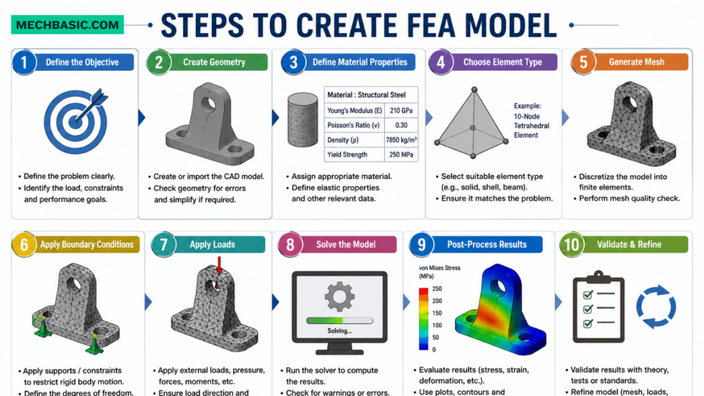
Creating an FEA (Finite Element Analysis) model involves preparing a CAD model, defining material properties, applying loads and boundary conditions, generating a mesh, solving the model, and evaluating the simulation results to verify the design.
Steps to Create an FEA Model:
- Create or Import CAD Model – Design the part or assembly using CAD software.
- Assign Material Properties – Specify material properties such as Young’s modulus, Poisson’s ratio, and density.
- Define Boundary Conditions – Apply supports, constraints, and fixtures.
- Apply Loads – Add forces, pressure, torque, gravity, or temperature loads.
- Generate Mesh – Divide the model into small finite elements for numerical analysis.
- Run the Solver – Compute the structural or thermal response of the model.
- Review Results – Analyze stress, strain, displacement, deformation, and factor of safety.
- Optimize the Design – Modify the design if necessary and repeat the analysis.
Key Inputs for FEA:
An FEA model requires geometry, material properties, boundary conditions, loads, mesh settings, and solver parameters to accurately simulate real-world behavior.
Expected Outputs:
FEA provides results such as stress distribution, strain, displacement, deformation, reaction forces, temperature distribution, natural frequencies, fatigue life, and factor of safety.
Common FEA Workflow:
CAD Model → Material Selection → Boundary Conditions → Load Application → Mesh Generation → Solve → Post-Processing → Design Optimization
In this article:
- How to Create an FEA Model:
- How to Create an FEA Model
- Steps to Create an FEA Model
- Step 1: Define the Engineering Problem
- Step 2: Create or Import the CAD Model
- Step 3: Simplify the Geometry
- Step 4: Assign Material Properties
- Step 5: Generate the Mesh
- Step 6: Apply Boundary Conditions
- Step 7: Apply Loads
- Step 8: Select the Analysis Type
- Step 9: Solve the Model
- Step 10: Review and Interpret Results
- Step 11: Validate the Results
- Step 1: Define the Engineering Problem
- Key Inputs for FEA
- Common FEA Workflow
- Best Practices for Creating an FEA Model
- Common Mistakes to Avoid
- Summary Table
- Frequently Asked Questions (FAQs)
- Conclusion
How to Create an FEA Model
Introduction
Creating a Finite Element Analysis (FEA) model is a systematic process used to simulate the behavior of a component or structure under real-world conditions before manufacturing. An FEA model combines geometry, material properties, mesh, loads, boundary conditions, and solver settings to predict how a design will respond to forces, pressure, temperature, vibration, or other operating conditions.
A well-prepared FEA model helps engineers identify design flaws, optimize product performance, reduce development costs, and improve safety. The accuracy of an FEA model depends on the quality of the input data and the correctness of the modeling assumptions.
How to Create an FEA Model
Creating an FEA model generally involves the following stages:
- Define the engineering problem.
- Create or import the CAD geometry.
- Simplify the geometry if necessary.
- Assign material properties.
- Generate the finite element mesh.
- Apply boundary conditions.
- Apply external loads.
- Select the appropriate analysis type.
- Solve the model.
- Review and validate the results.
Each stage plays a critical role in obtaining reliable simulation results.
Steps to Create an FEA Model
Step 1: Define the Engineering Problem
Before starting the analysis, clearly identify:
- Objective of the analysis
- Type of loading
- Operating conditions
- Expected performance
- Failure criteria
- Design constraints
Example
Analyze whether a steel bracket can safely support a 5 kN vertical load.
Step 2: Create or Import the CAD Model
The geometry is the foundation of the FEA model.
Models can be created using CAD software such as:
- SolidWorks
- AutoCAD
- CATIA
- Siemens NX
- Creo
- Fusion 360
Or imported using formats such as:
- STEP
- IGES
- Parasolid
- SolidWorks Part
- Inventor
- DWG (for 2D models)
Step 3: Simplify the Geometry
Remove unnecessary features that do not significantly affect the analysis.
Examples include:
- Small fillets
- Tiny holes
- Decorative features
- Logos
- Threads
- Small chamfers
Simplifying the model reduces mesh size and improves solution speed.
Step 4: Assign Material Properties
Accurate material properties are essential for meaningful results.
Typical properties include:
- Young’s Modulus
- Poisson’s Ratio
- Density
- Yield Strength
- Ultimate Tensile Strength
- Thermal Conductivity
- Specific Heat
- Coefficient of Thermal Expansion
Example
Material: Structural Steel
- Young’s Modulus = 200 GPa
- Poisson’s Ratio = 0.30
- Density = 7850 kg/m³
Step 5: Generate the Mesh
Meshing divides the model into many small finite elements connected by nodes.
Common Element Types
- Triangular
- Quadrilateral
- Tetrahedral
- Hexahedral
- Beam
- Shell
Mesh Considerations
- Fine mesh → Higher accuracy
- Coarse mesh → Faster solution
- Refine mesh near stress concentrations
- Perform mesh convergence studies for critical analyses
Step 6: Apply Boundary Conditions
Boundary conditions define how the model is supported or constrained.
Examples include:
- Fixed support
- Roller support
- Hinged support
- Symmetry condition
- Sliding support
Correct boundary conditions are essential to represent real operating conditions accurately.
Step 7: Apply Loads
Loads simulate real-world operating forces acting on the model.
Common loads include:
- Force
- Pressure
- Torque
- Gravity
- Temperature
- Centrifugal force
- Wind load
- Fluid pressure
Loads should reflect actual service conditions.
Step 8: Select the Analysis Type
Choose the analysis based on the engineering problem.
Common Analysis Types
- Static Structural
- Thermal
- Modal
- Harmonic
- Dynamic
- Fatigue
- Buckling
- Nonlinear
- Contact Analysis
- Multiphysics
Step 9: Solve the Model
The FEA solver assembles and solves the governing mathematical equations for all finite elements.
The software calculates:
- Stress
- Strain
- Displacement
- Temperature
- Reaction forces
- Natural frequencies
- Factor of Safety
Step 10: Review and Interpret Results
After solving, analyze the simulation results carefully.
Typical outputs include:
- Von Mises Stress
- Principal Stress
- Displacement
- Strain
- Reaction Forces
- Temperature Distribution
- Deformation
- Safety Factor
Compare the results with allowable design limits and engineering standards.
Step 11: Validate the Results
Validation ensures that simulation results are reliable.
Methods include:
- Analytical calculations
- Experimental testing
- Published data
- Engineering handbooks
- Previous project results
If significant differences are found, refine the model and repeat the analysis.
Key Inputs for FEA
An accurate FEA model requires several essential inputs.
1. Geometry
- 2D drawing
- 3D CAD model
- Assembly model
2. Material Properties
- Elastic modulus
- Density
- Yield strength
- Thermal properties
- Plasticity data (if required)
3. Mesh
- Element type
- Element size
- Mesh quality
- Node locations
4. Boundary Conditions
- Supports
- Constraints
- Contact conditions
- Symmetry
5. Loads
- Forces
- Pressure
- Torque
- Gravity
- Temperature
- Dynamic loads
6. Analysis Settings
- Solver type
- Convergence criteria
- Time steps (for transient analysis)
- Nonlinear settings
Expected Outputs
An FEA simulation provides a variety of useful engineering results.
Structural Results
- Von Mises Stress
- Principal Stress
- Shear Stress
- Strain
- Total Deformation
- Directional Deformation
- Reaction Forces
Thermal Results
- Temperature Distribution
- Heat Flux
- Thermal Gradient
- Thermal Stress
Dynamic Results
- Natural Frequencies
- Mode Shapes
- Acceleration
- Velocity
Fatigue Results
- Fatigue Life
- Damage Factor
- Safety Factor
Buckling Results
- Critical Buckling Load
- Buckling Mode Shapes
Contact Results
- Contact Pressure
- Penetration
- Frictional Stress
Common FEA Workflow
The standard workflow followed by engineers is:
- Define the engineering problem.
- Create or import the CAD model.
- Simplify the geometry.
- Assign material properties.
- Generate the mesh.
- Apply boundary conditions.
- Apply loads.
- Choose the analysis type.
- Configure solver settings.
- Run the simulation.
- Review the results.
- Validate the results.
- Modify the design if necessary.
- Repeat the analysis until design requirements are satisfied.
Best Practices for Creating an FEA Model
- Use clean and accurate CAD geometry.
- Simplify unnecessary features before meshing.
- Use correct material data from reliable sources.
- Apply realistic loads and constraints.
- Refine the mesh near holes, fillets, and sharp corners.
- Check mesh quality before solving.
- Perform mesh convergence studies.
- Validate simulation results with analytical or experimental data.
- Document assumptions and boundary conditions.
- Interpret results using engineering judgment rather than relying solely on software output.
Common Mistakes to Avoid
- Using incorrect material properties.
- Applying unrealistic boundary conditions.
- Creating a mesh that is too coarse for critical regions.
- Ignoring contact definitions between parts.
- Overlooking stress concentrations.
- Assuming simulation results are always correct without validation.
- Neglecting mesh convergence studies.
- Misinterpreting localized stress peaks caused by modeling artifacts.
Summary Table
| Aspect | Description |
|---|---|
| Purpose | Simulate real-world behavior of components before manufacturing |
| Main Inputs | Geometry, materials, mesh, loads, boundary conditions |
| Common Analysis Types | Static, Thermal, Modal, Fatigue, Buckling, Dynamic, Nonlinear |
| Key Outputs | Stress, strain, deformation, temperature, vibration, safety factor |
| Validation | Analytical calculations, experiments, engineering standards |
Frequently Asked Questions (FAQs)
1. What is an FEA model?
An FEA model is a digital representation of a component or structure used to simulate its behavior under different physical conditions using the Finite Element Method.
2. Why is meshing important in an FEA model?
Meshing divides the geometry into smaller elements so that the governing equations can be solved numerically. A well-designed mesh improves the accuracy and reliability of the simulation.
3. What are the essential inputs for an FEA model?
The key inputs include geometry, material properties, mesh, loads, boundary conditions, contact definitions (if applicable), and solver settings.
4. What types of results can an FEA model produce?
Typical results include stress, strain, displacement, reaction forces, temperature distribution, natural frequencies, fatigue life, and factor of safety.
5. Why is geometry simplification important?
Removing unnecessary features such as tiny holes, cosmetic fillets, or logos reduces computational time and improves solver efficiency without significantly affecting analysis accuracy.
6. How do boundary conditions affect FEA results?
Boundary conditions define how the model is constrained and loaded. Incorrect boundary conditions can produce unrealistic or misleading results.
7. What is mesh convergence?
Mesh convergence is the process of refining the mesh until further refinement produces negligible changes in the results, ensuring solution accuracy.
8. Can FEA completely replace physical testing?
No. FEA greatly reduces the need for prototypes, but physical testing is still required to validate simulation results, particularly for safety-critical applications.
9. Which software can be used to create an FEA model?
Common FEA software includes ANSYS, Abaqus, SolidWorks Simulation, COMSOL Multiphysics, Siemens Simcenter 3D, MSC Nastran, Autodesk Inventor Nastran, and Fusion 360 Simulation.
10. What determines the accuracy of an FEA model?
Accuracy depends on high-quality geometry, correct material properties, appropriate mesh density, realistic loads and boundary conditions, proper solver settings, and validation against analytical or experimental results.
Conclusion
Creating an effective FEA model involves more than importing a CAD design into simulation software. It requires careful definition of the engineering problem, accurate material data, appropriate mesh generation, realistic loading and boundary conditions, and thoughtful interpretation of results. By following a structured workflow and validating the simulation against analytical calculations or experimental data, engineers can confidently use FEA to optimize designs, improve safety, reduce costs, and accelerate product development. A well-built FEA model is a powerful decision-making tool that supports the design of reliable and efficient engineering products across a wide range of industries.
SimScale: Guide for FEA & Step-by-Step Modeling: Detailed walkthrough covering geometry preparation, meshing strategy, boundary condition assignment, and post-processing.
Latest articles:

Best Budget Workstation Laptops for SolidWorks and Heavy 3D Assembly Modeling
Best Budget Workstation Laptops for SolidWorks and Heavy 3D Assembly Modeling Overview What Does SOLIDWORKS…

SolidWorks Standard vs Professional vs Premium: Full Feature Comparison
SolidWorks Standard vs Professional vs Premium: Full Feature Comparison Overview: SOLIDWORKS Package Overview SOLIDWORKS comes…

SolidWorks 2026 License Cost: Perpetual vs Subscription Pricing Breakdown
SolidWorks 2026 License Cost: Perpetual vs Subscription Pricing Breakdown Overview: SOLIDWORKS 2026 License Options SOLIDWORKS…

Flatness-GD&T | GD&T Tutorials

ANSI vs ISO Standards-Key Differences you need to know

Straightness-GD&T | GD&T Tutorials
Categories:




















