
Key Takeaways:
SOLIDWORKS Flow Simulation
What is SOLIDWORKS Flow Simulation?
SOLIDWORKS Flow Simulation is a Computational Fluid Dynamics (CFD) tool integrated with SOLIDWORKS that allows engineers to simulate fluid flow, heat transfer, pressure, and temperature directly on 3D CAD models. It helps evaluate product performance without building physical prototypes.
Key Features:
SOLIDWORKS Flow Simulation provides tools for internal and external flow analysis, heat transfer, turbulence modeling, pressure drop, fluid mixing, particle studies, and thermal analysis.
How It Works:
The typical workflow is CAD Model → Select Fluid → Define Materials → Apply Boundary Conditions → Create Computational Mesh → Run Simulation → Analyze Results.
Applications:
It is used for cooling systems, pumps, valves, fans, heat exchangers, HVAC equipment, electronics cooling, automotive components, and aerodynamic studies.
Advantages:
SOLIDWORKS Flow Simulation allows engineers to test designs virtually, identify flow and thermal problems early, optimize product performance, reduce physical prototypes, and shorten development time.
Key Takeaway
CAD Model → Fluid & Materials → Boundary Conditions → Mesh → Solve → Results → Design Optimization
In this article:
SOLIDWORKS Flow Simulation
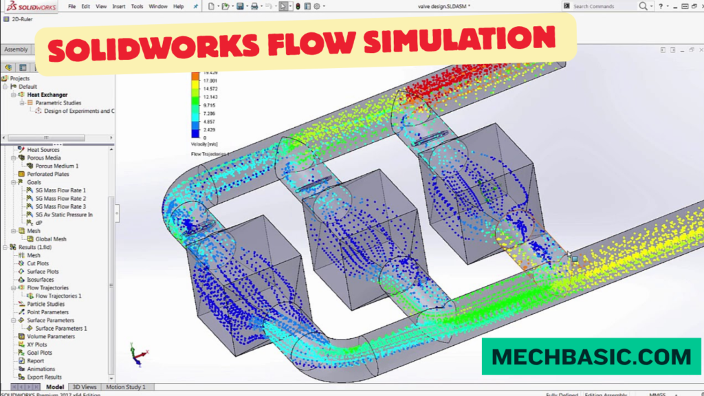
SOLIDWORKS Flow Simulation is a computational fluid dynamics (CFD) tool integrated with SOLIDWORKS. It allows engineers and designers to simulate fluid flow, heat transfer, pressure, temperature, and fluid forces directly within the SOLIDWORKS environment.
Instead of building a physical prototype for every design iteration, engineers can use Flow Simulation to virtually investigate how air, water, gases, and other fluids behave around or inside a product.
It is commonly used for cooling systems, pumps, valves, HVAC equipment, electronics, enclosures, piping, fans, and other mechanical products.
What is SOLIDWORKS Flow Simulation?
SOLIDWORKS Flow Simulation is an integrated CFD solution that uses numerical methods to predict fluid behavior and thermal performance.
It can analyze how fluids:
- Flow through components
- Move around objects
- Change pressure
- Transfer heat
- Interact with solid materials
- Behave in internal and external flow environments
The results can help engineers optimize a design before manufacturing.
Typical CFD Workflow
SOLIDWORKS CAD Model
↓
Define Fluid & Materials
↓
Create Computational Domain
↓
Apply Boundary Conditions
↓
Generate Mesh
↓
Run Simulation
↓
Analyze Results
↓
Optimize Design
SOLIDWORKS Flow Simulation Capabilities Guide: Official documentation detailing boundary condition definitions, fluid subdomains, radiation models, fan curves, and cut/trajectory plot setups.
Key Features
1. Internal Flow Analysis
Flow Simulation can analyze fluid moving inside a component or system.
Examples:
- Pipes
- Valves
- Pumps
- Manifolds
- Heat exchangers
- Cooling channels
Engineers can investigate:
- Pressure drop
- Velocity
- Flow rate
- Temperature
2. External Flow Analysis
External flow analysis studies fluid moving around a component.
Examples:
- Airflow around vehicles
- Airflow around equipment
- Wind effects on components
- Cooling air around electronics
It can help determine:
- Drag
- Pressure distribution
- Velocity distribution
- Flow separation
3. Heat Transfer Analysis
SOLIDWORKS Flow Simulation can simulate thermal behavior involving:
- Conduction
- Convection
- Radiation in supported scenarios
This makes it useful for thermal-management problems.
Applications:
- Electronics cooling
- Heat sinks
- Motors
- Engines
- Industrial equipment
4. Fluid Flow
The software can simulate different types of fluid behavior, including flow through complex geometries.
Engineers can visualize:
- Streamlines
- Velocity fields
- Pressure fields
- Temperature distribution
5. Turbulence Modeling
Flow Simulation can account for turbulent flow using appropriate turbulence models.
This is important for many practical engineering applications involving:
- High-speed airflow
- Industrial piping
- Fans
- Pumps
- HVAC systems
6. Goal-Based Analysis
Engineers can define Goals to monitor important engineering quantities during a simulation.
Examples include:
- Pressure
- Temperature
- Velocity
- Mass flow rate
- Force
- Torque
This makes it easier to determine whether a design meets its performance requirements.
7. Parametric Studies
Design alternatives can be evaluated by changing parameters such as:
- Geometry
- Flow rate
- Temperature
- Material
- Operating conditions
This can help engineers identify a better-performing design.
8. Rotating Equipment
Flow Simulation can be used for certain rotating-flow applications.
Examples include:
- Fans
- Pumps
- Impellers
- Rotating machinery
This allows engineers to study the interaction between rotating components and fluid flow.
How It Works
Step 1: Create the CAD Model
The first step is to create the component or assembly in SOLIDWORKS.
For example:
Cooling Channel → Pipe → Heat Sink → Fan Housing
The CAD model becomes the basis for the CFD simulation.
Step 2: Start a Flow Simulation Project
Create a new Flow Simulation project and define the simulation settings.
Important parameters include:
- Analysis type
- Fluid
- Units
- Computational domain
- Physical models
Step 3: Select the Fluid
Choose the appropriate fluid from the available engineering database.
Examples include:
- Air
- Water
- Oil
- Various gases
- Other supported fluids
Fluid properties influence the simulation results.
Step 4: Define Materials
For thermal simulations, define the materials used in the solid components.
Material properties can include:
- Thermal conductivity
- Density
- Specific heat
These properties influence heat-transfer predictions.
Step 5: Define Boundary Conditions
Boundary conditions describe how the system interacts with its surroundings.
Examples include:
- Inlet velocity
- Volume flow rate
- Mass flow rate
- Pressure
- Temperature
- Wall conditions
Correct boundary conditions are essential for meaningful results.
Step 6: Create the Computational Domain
The computational domain defines the region in which the CFD calculations are performed.
For an internal flow problem, the domain may represent the fluid volume inside the component.
For an external flow problem, the domain surrounds the object being analyzed.
Step 7: Generate the Mesh
The computational domain is divided into many smaller elements or cells.
The solver calculates the governing equations across these cells.
Mesh refinement can be increased in areas such as:
- Small passages
- Sharp geometry changes
- Boundary layers
- High-gradient regions
- Narrow gaps
Step 8: Run the Simulation
The solver performs numerical calculations to determine the flow and thermal fields.
Depending on the project, the simulation may calculate:
- Pressure
- Velocity
- Temperature
- Density
- Forces
- Heat transfer
Step 9: Analyze the Results
After solving, engineers can visualize results using tools such as:
- Cut plots
- Surface plots
- Flow trajectories
- Streamlines
- Isosurfaces
- XY plots
These results help identify design problems and performance limitations.
Applications
1. Electronics Cooling
Flow Simulation can be used to study:
- Heat sinks
- Fans
- Electronic enclosures
- Circuit-board cooling
- Battery thermal management
Engineers can determine whether components remain within acceptable temperature limits.
2. HVAC
Applications include:
- Air ducts
- Ventilation systems
- Air conditioning
- Cooling systems
- Room airflow
Engineers can investigate airflow distribution and temperature uniformity.
3. Automotive
Applications include:
- Engine cooling
- Radiators
- Vehicle airflow
- Cabin ventilation
- Battery cooling
4. Pumps and Valves
Flow Simulation can help analyze:
- Pressure drop
- Flow distribution
- Velocity
- Cavitation-related conditions in applicable analyses
- Pump and valve performance
5. Heat Exchangers
Engineers can study:
- Fluid temperature changes
- Heat transfer
- Flow distribution
- Pressure drop
This helps improve thermal performance.
6. Industrial Equipment
Applications include:
- Compressors
- Fans
- Blowers
- Machinery cooling
- Hydraulic components
- Process equipment
7. Aerospace
Flow Simulation can support studies involving:
- Cooling
- Internal airflow
- Component aerodynamics
- Thermal management
For highly specialized aerospace aerodynamics, however, engineers may use more specialized CFD tools depending on the complexity and required fidelity.
Advantages
1. Integrated With SOLIDWORKS
One of the biggest advantages is that the CFD workflow is integrated with the SOLIDWORKS CAD environment.
You can modify the CAD model and investigate the impact of design changes without building the entire model in a separate CAD system.
2. Reduces Physical Prototypes
Virtual simulations can reduce the number of physical prototypes required during development.
This can save:
- Time
- Materials
- Testing costs
- Development effort
3. Faster Design Optimization
Engineers can test different designs virtually.
For example:
Design A → Simulate
Design B → Simulate
Design C → Simulate
The results can then be compared to determine which design performs better.
4. Identifies Problems Early
CFD can reveal issues such as:
- Excessive pressure drop
- Poor cooling
- High temperatures
- Uneven flow
- Recirculation
- Flow restrictions
These problems can be addressed before manufacturing.
5. Visualizes Complex Flow
Flow Simulation provides visual representations of otherwise invisible fluid behavior.
Engineers can see:
- Where fluid accelerates
- Where pressure increases
- Where heat accumulates
- How flow travels through a system
6. Supports Thermal Design
The combination of fluid-flow and heat-transfer analysis makes it useful for thermal-management applications.
Important CFD Parameters
When setting up a Flow Simulation project, engineers should pay particular attention to:
Fluid Properties
- Density
- Viscosity
- Specific heat
- Thermal conductivity
Boundary Conditions
- Pressure
- Temperature
- Velocity
- Mass flow
- Volume flow
Geometry
- Fluid passages
- Gaps
- Sharp edges
- Complex features
Mesh
- Global refinement
- Local refinement
- Boundary-layer resolution
- Critical geometry regions
Solver Settings
- Convergence criteria
- Physical models
- Time dependence
- Numerical settings
SOLIDWORKS Flow Simulation vs Traditional CFD
| Feature | Flow Simulation | Specialized CFD |
|---|---|---|
| SOLIDWORKS integration | Excellent | Usually separate |
| CAD workflow | Easy | May require geometry transfer |
| Mechanical design studies | Excellent | Excellent |
| Basic-to-intermediate CFD | Excellent | Excellent |
| Highly specialized CFD | Depends on application | Often stronger |
| Ease of setup | High | Varies |
| Design iteration | Fast | Varies |
| Advanced multiphysics | Depends on application | Often broader |
The appropriate CFD tool depends on the complexity, physics, accuracy requirements, and industry standards of the project.
Best Practices
1. Simplify the Geometry
Remove unnecessary CAD details that do not significantly affect the flow.
This can reduce computational cost.
2. Use Appropriate Boundary Conditions
Poor assumptions at the inlet, outlet, walls, or thermal boundaries can produce misleading results.
3. Refine the Mesh Where Needed
Do not rely only on a globally fine mesh. Pay particular attention to regions with strong gradients or important flow features.
4. Perform Mesh Independence Checks
Increase mesh resolution and determine whether the important engineering results remain sufficiently stable.
5. Check Conservation and Convergence
Make sure the solution has adequately converged and that important quantities such as mass flow and energy balance behave as expected.
6. Validate Important Results
For critical engineering applications, compare CFD predictions with:
- Experimental data
- Analytical calculations
- Published correlations
- Previous validated simulations
Frequently Asked Questions (FAQs)
1. What is SOLIDWORKS Flow Simulation used for?
It is used to simulate fluid flow and heat transfer in and around SOLIDWORKS designs.
2. Can SOLIDWORKS Flow Simulation analyze airflow?
Yes. Airflow can be analyzed for applications such as cooling, ventilation, electronics, ducts, and external flow.
3. Can it simulate water flow?
Yes. Water and other supported fluids can be used for appropriate flow analyses.
4. Can it perform heat-transfer analysis?
Yes. It can analyze thermal behavior involving fluid flow and heat transfer, including conjugate heat-transfer problems.
5. Is Flow Simulation the same as SOLIDWORKS Simulation?
No.
SOLIDWORKS Simulation primarily focuses on structural and related mechanical analyses, while SOLIDWORKS Flow Simulation focuses on fluid flow and thermal-fluid behavior.
6. Can Flow Simulation replace physical testing?
No. CFD is a powerful engineering prediction tool, but important designs should be validated with appropriate analytical or experimental evidence.
Conclusion
SOLIDWORKS Flow Simulation provides an integrated CFD environment for analyzing fluid flow, pressure, velocity, temperature, and heat transfer directly within the SOLIDWORKS design workflow.
The typical process is:
Create CAD Model → Define Fluid & Materials → Set Boundary Conditions → Create Domain → Generate Mesh → Run Simulation → Analyze Results → Optimize Design
Its major advantages include CAD integration, faster design iteration, reduced prototype requirements, visualization of fluid behavior, and thermal-flow analysis.
For engineers who already use SOLIDWORKS, Flow Simulation is particularly useful for bringing CFD analysis into the mechanical design process, helping them identify fluid and thermal problems before moving to physical manufacturing and testing.
Latest articles:

Best Budget Workstation Laptops for SolidWorks and Heavy 3D Assembly Modeling
Best Budget Workstation Laptops for SolidWorks and Heavy 3D Assembly Modeling Overview What Does SOLIDWORKS…

SolidWorks Standard vs Professional vs Premium: Full Feature Comparison
SolidWorks Standard vs Professional vs Premium: Full Feature Comparison Overview: SOLIDWORKS Package Overview SOLIDWORKS comes…

SolidWorks 2026 License Cost: Perpetual vs Subscription Pricing Breakdown
SolidWorks 2026 License Cost: Perpetual vs Subscription Pricing Breakdown Overview: SOLIDWORKS 2026 License Options SOLIDWORKS…

Flatness-GD&T | GD&T Tutorials

ANSI vs ISO Standards-Key Differences you need to know

Straightness-GD&T | GD&T Tutorials
Related Tags:
Categories:




















