
Key Takeaways:
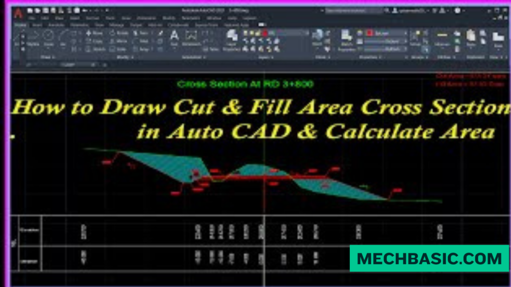
How to Do Cut & Fill Calculations in AutoCAD
Cut and fill calculation determines how much earth needs to be removed (cut) or added (fill) to achieve a proposed ground level. It is commonly used in road, site, grading, and land-development projects.
Basic Workflow
1. Create the Existing Ground Surface
- Import or enter your survey/topographic points.
- Create an Existing Ground (EG) Surface from the elevation data.
2. Create the Proposed Surface
- Create your proposed grading, road, platform, or finished ground levels.
- Build a Finished Ground (FG) Surface.
3. Create a Volume Surface
In Civil 3D, go to:
Toolspace → Prospector → Surfaces → Create Surface
Choose TIN Volume Surface and set:
- Base Surface: Existing Ground (EG)
- Comparison Surface: Finished Ground (FG)
4. Calculate Cut & Fill Volumes
Open the volume information for the volume surface. Civil 3D calculates:
- Cut Volume → Earth that must be removed
- Fill Volume → Earth that must be added
- Net Volume → Difference between cut and fill
Example
Suppose the volume calculation gives:
| Quantity | Volume |
|---|---|
| Cut | 2,500 m³ |
| Fill | 1,800 m³ |
| Net | 700 m³ |
This means approximately 700 m³ more material is being removed than added.
Grid Method – Basic AutoCAD Calculation
If you’re using standard AutoCAD rather than Civil 3D, you can calculate volumes manually using the grid method:
Volume = Area × Average Depth
For each grid cell:
Cut/Fill Volume = Grid Area × Average Elevation Difference
Then add the volumes of all grid cells.
Important: AutoCAD vs. Civil 3D
AutoCAD: Requires manual calculations or custom tools/workflows for terrain volume calculations.
Civil 3D: Recommended for professional cut-and-fill work because it can create surfaces, volume surfaces, contour maps, and automated cut/fill reports.
Key Takeaway
Survey Data → Existing Surface → Proposed Surface → Volume Surface → Cut & Fill Volumes → Earthwork Report
In this article:
- How to Do Cut and Fill Calculations in AutoCAD
- 1. Prepare the Existing Ground Data
- 2. Create the Proposed Ground Level
- 3. Calculate the Difference in Elevation
- 4. Example of Cut and Fill
- 5. Calculate Cut and Fill Volumes
- 6. Calculate the Net Earthwork
- 7. Using AutoCAD for Basic Calculations
- 8. Use Civil 3D for Automated Cut and Fill
- 9. Create the Existing Ground Surface
- 10. Create the Proposed Surface
- 11. Compare the Two Surfaces
- 12. Create a Volume Surface
- 13. Example: Site Grading Project
- 14. Cut and Fill Map
- 15. Important Factors Affecting Cut and Fill
- 16. Cut and Fill Calculation Methods
- 17. Grid Method
- 18. Average End Area Method
- 19. Common AutoCAD/Civil 3D Workflow
- Frequently Asked Questions (FAQs)
- Conclusion
How to Do Cut and Fill Calculations in AutoCAD
Cut and fill calculations are used in civil engineering and site development to determine how much soil or material must be removed (cut) or added (fill) to achieve a proposed ground level.
The basic concept is:
- Cut → Existing ground is higher than the proposed surface.
- Fill → Existing ground is lower than the proposed surface.
AutoCAD by itself can help with the drafting and measurement, but AutoCAD Civil 3D is generally the better Autodesk tool for automated terrain, surface, and cut/fill volume calculations.
Autodesk Learn: Balance Cut and Fill Volumes: Official tutorial explaining how to adjust grading group elevations and optimize net earthwork volumes.
1. Prepare the Existing Ground Data
Before calculating cut and fill, you need accurate existing ground elevations.
Common sources include:
- Survey points
- Spot elevations
- Contours
- Total station data
- GPS/GNSS survey data
- Point files
- Existing surface models
For example:
| Point | Existing Elevation |
|---|---|
| P1 | 102.50 m |
| P2 | 101.80 m |
| P3 | 103.20 m |
| P4 | 102.10 m |
These elevations represent the existing terrain.
2. Create the Proposed Ground Level
Next, define the proposed surface or finished ground level.
This could be:
- A flat platform
- A sloped site
- A road profile
- A building pad
- A parking area
- A drainage surface
For example, suppose the proposed finished level is:
102.00 m
3. Calculate the Difference in Elevation
The basic cut/fill calculation is:
Elevation Difference = Existing Elevation − Proposed Elevation
If the result is positive:
Cut
If the result is negative:
Fill
Example
Existing elevation:
103.20 m
Proposed elevation:
102.00 m
Therefore:
103.20 − 102.00 = 1.20 m
The location requires:
1.20 m of Cut
4. Example of Cut and Fill
Suppose you have four survey points.
| Point | Existing Ground | Proposed Level | Difference | Requirement |
|---|---|---|---|---|
| P1 | 102.50 m | 102.00 m | +0.50 m | Cut |
| P2 | 101.80 m | 102.00 m | -0.20 m | Fill |
| P3 | 103.20 m | 102.00 m | +1.20 m | Cut |
| P4 | 102.10 m | 102.00 m | +0.10 m | Cut |
This provides a simple indication of where material needs to be removed or added.
However, volume requires considering the area and variation in elevation across the site.
5. Calculate Cut and Fill Volumes
A simple approximation for a small area is:
Volume = Area × Average Depth
Example
Suppose an area is:
1,000 m²
and the average cut depth is:
0.50 m
Then:
Cut Volume = 1,000 × 0.50
= 500 m³
Similarly, if another area has an average fill depth of:
0.30 m
then:
Fill Volume = 1,000 × 0.30
= 300 m³
6. Calculate the Net Earthwork
Once cut and fill volumes are known:
Net Earthwork = Cut Volume − Fill Volume
For example:
Cut = 500 m³
Fill = 300 m³
Therefore:
Net = 500 − 300 = 200 m³
This indicates that approximately 200 m³ more material is being removed than added, before considering factors such as compaction, bulking, shrinkage, and material suitability.
7. Using AutoCAD for Basic Calculations
Standard AutoCAD can help you prepare the drawing and perform basic measurements.
Useful commands include:
DIST
Measures the distance between two points.
AREA
Calculates the area of a closed boundary.
LIST
Displays object information.
ID
Reports the coordinates of a selected point.
PROPERTIES
Displays geometric and object information.
These tools can be useful for manual or simplified calculations.
8. Use Civil 3D for Automated Cut and Fill
For professional earthwork calculations, Autodesk Civil 3D is generally more appropriate than standard AutoCAD.
Civil 3D can create and compare surfaces.
Typical workflow:
Survey Data → Existing Ground Surface → Proposed Surface → Surface Comparison → Cut/Fill Volumes
9. Create the Existing Ground Surface
In Civil 3D:
- Import survey points.
- Create a TIN surface.
- Add point data.
- Add breaklines where required.
- Add boundaries.
- Verify the existing surface.
This creates the Existing Ground (EG) surface.
10. Create the Proposed Surface
Create another surface representing the finished design.
This may be based on:
- Feature lines
- Grading
- Corridors
- Building pads
- Road designs
- Proposed contours
This becomes the Finished Ground (FG) or proposed surface.
11. Compare the Two Surfaces
Civil 3D can compare the existing and proposed surfaces to determine elevation differences.
Conceptually:
FG − EG
The resulting difference identifies areas where the proposed surface is above or below the existing terrain.
Depending on the comparison convention:
- Areas requiring excavation represent cut
- Areas requiring material placement represent fill
Always check the software’s surface comparison settings and sign convention.
12. Create a Volume Surface
A TIN Volume Surface can be created between the existing and proposed surfaces.
The volume surface compares:
Existing Ground ↔ Proposed Ground
It can provide:
- Cut volume
- Fill volume
- Net volume
This is much more reliable for real projects than calculating volume from only a few spot elevations.
13. Example: Site Grading Project
Suppose a proposed building platform is being created.
Existing Ground
The survey indicates elevations ranging from:
100.50 m to 103.00 m
Proposed Ground
The building platform is designed at:
102.00 m
Some areas are above 102.00 m and therefore require excavation.
Other areas are below 102.00 m and require filling.
After creating the existing and proposed surfaces, Civil 3D might produce a result such as:
| Earthwork | Volume |
|---|---|
| Cut | 2,450 m³ |
| Fill | 1,800 m³ |
| Net Cut | 650 m³ |
The actual values would come from the project’s surface data, not from the example.
14. Cut and Fill Map
A useful way to visualize earthwork is with a cut/fill map.
Different colors can represent:
- Cut areas
- Fill areas
- Areas close to grade
This makes it easy for engineers and contractors to understand where excavation or imported material is required.
15. Important Factors Affecting Cut and Fill
The calculated volume is not always equal to the amount of material that must be transported.
Consider:
1. Compaction
Fill material becomes denser after compaction.
2. Bulking
Excavated soil may occupy a larger volume after being disturbed.
3. Shrinkage
Some materials lose volume when compacted.
4. Soil Type
Clay, sand, rock, and mixed materials behave differently.
5. Unsuitable Material
Some excavated material may not be suitable for reuse as structural fill.
6. Topsoil
Topsoil stripping may need to be calculated separately.
7. Rock Excavation
Rock excavation can require separate quantities and construction methods.
16. Cut and Fill Calculation Methods
| Method | Suitable For |
|---|---|
| Area × Average Depth | Simple/small areas |
| Grid Method | Preliminary earthwork estimates |
| Average End Area | Roads and linear projects |
| TIN Surface Comparison | Complex terrain/site grading |
| Civil 3D Volume Surface | Professional CAD-based earthwork |
17. Grid Method
For larger sites, the area can be divided into a grid.
For each grid point, determine:
Existing Elevation
and
Proposed Elevation
Then calculate the elevation difference.
The volume for each grid cell can be estimated based on its area and average depth.
The individual cell volumes are then added together.
This method is useful for understanding the basic principles of earthwork calculations.
18. Average End Area Method
The Average End Area Method is commonly used for linear projects such as:
- Roads
- Railways
- Canals
- Trenches
- Embankments
The basic formula is:
V = (A₁ + A₂) / 2 × L
Where:
- V = Volume
- A₁ = Area of first cross-section
- A₂ = Area of second cross-section
- L = Distance between sections
Example
If:
A₁ = 100 m²
A₂ = 140 m²
L = 20 m
Then:
V = (100 + 140) / 2 × 20
V = 2,400 m³
19. Common AutoCAD/Civil 3D Workflow
For a typical site:
Survey Data
↓
Existing Ground Surface
↓
Proposed Design
↓
Proposed Ground Surface
↓
Compare Surfaces
↓
Calculate Cut & Fill
↓
Generate Volume Report
↓
Prepare Earthwork Plan
This workflow provides a more complete understanding of the project’s earthwork requirements.
Frequently Asked Questions (FAQs)
1. Can AutoCAD calculate cut and fill?
Basic AutoCAD can be used for manual area, distance, elevation, and simplified volume calculations. For automated terrain-based cut/fill analysis, Civil 3D is generally the better choice.
2. What is the formula for cut and fill?
For a simple area:
Volume = Area × Average Depth
For complex terrain, surface-based volume calculations are preferred.
3. What is cut?
Cut is the amount of existing material that must be removed because the existing ground is above the proposed elevation.
4. What is fill?
Fill is the material required where the existing ground is below the proposed elevation.
5. What is a volume surface?
A volume surface compares two surfaces, such as Existing Ground and Finished Ground, to determine earthwork quantities.
6. Is cut and fill calculation important in civil engineering?
Yes. It helps estimate excavation, imported fill, hauling requirements, construction costs, and overall site grading requirements.
Conclusion
Cut and fill calculations determine how much earth needs to be excavated and how much material needs to be placed to achieve a proposed terrain or grading design.
Basic Method
Existing Elevation − Proposed Elevation
→ Positive = Cut
→ Negative = Fill
For simple areas, volume can be estimated using:
Volume = Area × Average Depth
For professional projects involving irregular terrain, the preferred workflow is:
Survey Data → Existing Surface → Proposed Surface → Volume Surface → Cut/Fill Volumes
For complex civil projects, Civil 3D surface-based calculations provide a much more practical and accurate approach than manually calculating every point in standard AutoCAD.
Latest articles:

Best Budget Workstation Laptops for SolidWorks and Heavy 3D Assembly Modeling
Best Budget Workstation Laptops for SolidWorks and Heavy 3D Assembly Modeling Overview What Does SOLIDWORKS…

SolidWorks Standard vs Professional vs Premium: Full Feature Comparison
SolidWorks Standard vs Professional vs Premium: Full Feature Comparison Overview: SOLIDWORKS Package Overview SOLIDWORKS comes…

SolidWorks 2026 License Cost: Perpetual vs Subscription Pricing Breakdown
SolidWorks 2026 License Cost: Perpetual vs Subscription Pricing Breakdown Overview: SOLIDWORKS 2026 License Options SOLIDWORKS…

Flatness-GD&T | GD&T Tutorials

ANSI vs ISO Standards-Key Differences you need to know

Straightness-GD&T | GD&T Tutorials
Categories:




















