
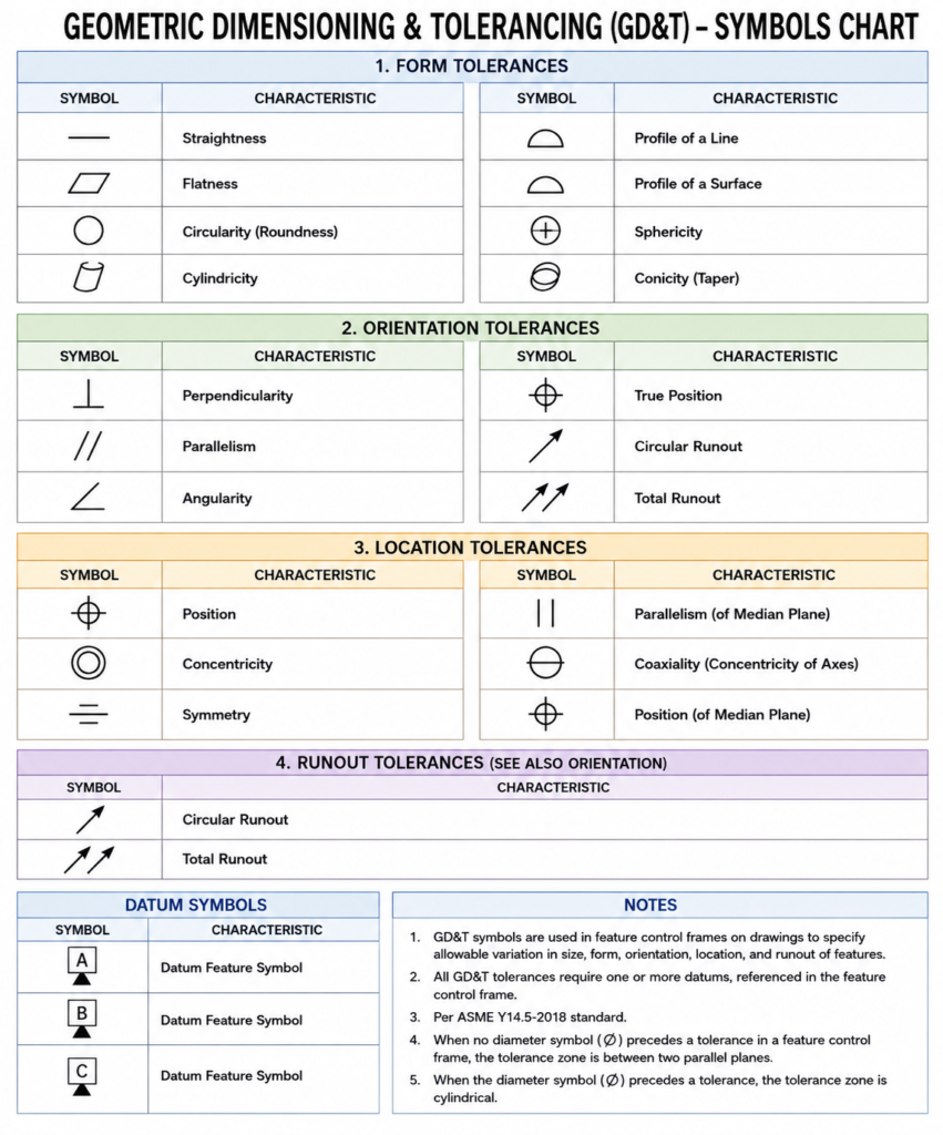
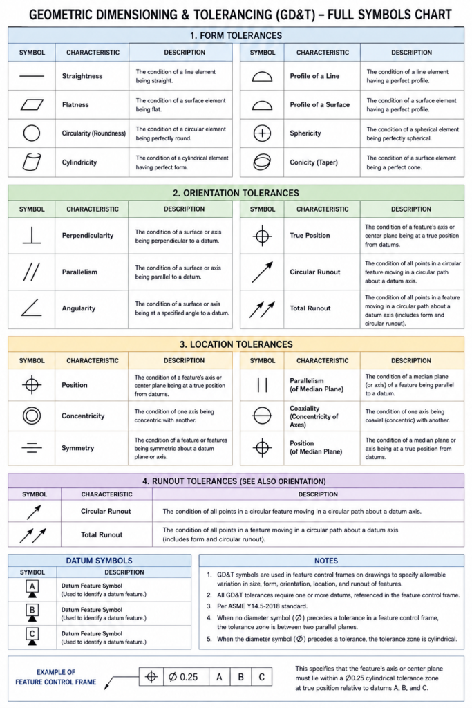
Geometric Dimensioning and Tolerancing (GD&T) is a standardized system used in engineering drawings to define the allowable variation in a part’s geometry. GD&T symbols help engineers, designers, machinists, and inspectors clearly communicate requirements for size, form, orientation, location, and runout. This GD&T symbols chart provides a quick reference for understanding commonly used symbols and their meanings.
Conclusion:
A GD&T symbols chart is a useful reference for anyone working with technical drawings and precision manufacturing. By understanding these symbols, you can interpret engineering drawings more accurately, reduce manufacturing errors, and improve communication between design, production, and inspection teams. Download the free GD&T symbols chart and keep it handy for quick reference.
Pick the Best GD&T Course to Boost Your Career
Latest articles:

Best Budget Workstation Laptops for SolidWorks and Heavy 3D Assembly Modeling
Best Budget Workstation Laptops for SolidWorks and Heavy 3D Assembly Modeling Overview What Does SOLIDWORKS…

SolidWorks Standard vs Professional vs Premium: Full Feature Comparison
SolidWorks Standard vs Professional vs Premium: Full Feature Comparison Overview: SOLIDWORKS Package Overview SOLIDWORKS comes…

SolidWorks 2026 License Cost: Perpetual vs Subscription Pricing Breakdown
SolidWorks 2026 License Cost: Perpetual vs Subscription Pricing Breakdown Overview: SOLIDWORKS 2026 License Options SOLIDWORKS…

Flatness-GD&T | GD&T Tutorials

ANSI vs ISO Standards-Key Differences you need to know

Straightness-GD&T | GD&T Tutorials
Related Tags:
Categories:




















