
Key Takeaways:
What is FEA Analysis?
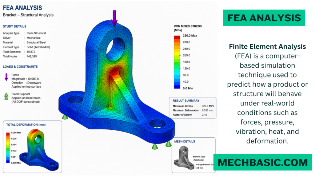
Finite Element Analysis (FEA) is a computer-based simulation technique used to predict how a product or structure will behave under real-world conditions such as forces, pressure, vibration, heat, and deformation. It helps engineers evaluate design performance before manufacturing, reducing cost and development time.
Advantages of FEA:
FEA improves design accuracy, reduces the need for physical prototypes, identifies potential failures early, optimizes product performance, and saves both time and manufacturing costs.
Applications of FEA:
FEA is widely used in the automotive, aerospace, civil, mechanical, biomedical, and manufacturing industries to analyze structural strength, stress, thermal behavior, fluid flow, vibration, and fatigue.
How FEA Works:
FEA divides a complex model into small elements called a mesh. Mathematical equations are solved for each element, and the combined results predict stress, strain, displacement, temperature, and other physical responses of the entire structure.
Common FEA Software:
Popular FEA software includes ANSYS, Abaqus, SolidWorks Simulation, COMSOL Multiphysics, MSC Nastran, Altair HyperWorks, and Autodesk Inventor Nastran.
Features of FEA:
FEA provides tools for stress analysis, deformation analysis, thermal analysis, vibration (modal) analysis, fatigue analysis, buckling analysis, and optimization, enabling engineers to design safer and more reliable products.
In this article:
FEA Analysis:
Finite Element Analysis (FEA) is a computer-based simulation method used to evaluate the behavior of components under various loads and conditions.
It divides a complex model into small finite elements to calculate stress, strain, deformation, and temperature distribution.
FEA helps engineers optimize designs, reduce development costs, and improve product safety and reliability.
FEA Analysis (Finite Element Analysis)
Introduction
Finite Element Analysis (FEA) is a powerful computer-based simulation technique used to predict how engineering components, products, and structures will behave under real-world conditions such as forces, pressure, temperature, vibration, impact, and fluid flow. It is based on the Finite Element Method (FEM), a numerical technique that divides a complex object into many small, manageable elements to simplify calculations.
FEA enables engineers to analyze the strength, durability, deformation, stress distribution, and overall performance of a design before manufacturing a physical prototype. This helps reduce development costs, improve product quality, shorten design cycles, and ensure safety and reliability.
Today, FEA is an indispensable tool in mechanical, civil, aerospace, automotive, biomedical, marine, and manufacturing engineering, supporting everything from small machine parts to large infrastructure projects.
What is FEA Analysis?
Finite Element Analysis (FEA) is a numerical simulation method used to evaluate the physical behavior of components and structures under different loading and environmental conditions. Instead of analyzing an entire object as one unit, FEA divides it into thousands or even millions of smaller elements connected by nodes. Mathematical equations are solved for each element, and the results are combined to predict the behavior of the complete model.
FEA is commonly used to analyze:
- Stress and strain
- Deformation
- Thermal behavior
- Vibration
- Fatigue life
- Buckling
- Fluid interaction
- Structural integrity
By using FEA, engineers can identify weak points, optimize designs, and improve product performance before production begins.
How FEA Works
The FEA process follows a systematic workflow:
Step 1: Create the Geometry
A 2D or 3D CAD model of the component or structure is created using CAD software such as AutoCAD, SolidWorks, CATIA, or Siemens NX.
Step 2: Define Material Properties
Material properties are assigned to the model, including:
- Young’s Modulus
- Poisson’s Ratio
- Density
- Yield Strength
- Thermal Conductivity
- Coefficient of Thermal Expansion
Accurate material properties are essential for reliable simulation results.
Step 3: Mesh Generation
The CAD model is divided into numerous small elements connected by nodes. This network is called the mesh.
Common element types include:
- Triangular elements
- Quadrilateral elements
- Tetrahedral elements
- Hexahedral elements
- Beam elements
- Shell elements
A finer mesh generally provides more accurate results but requires greater computational resources.
Step 4: Apply Boundary Conditions
Boundary conditions define how the model is constrained or supported.
Examples include:
- Fixed supports
- Roller supports
- Hinged supports
- Symmetry conditions
Step 5: Apply Loads
The operating conditions are applied to the model.
Examples include:
- Forces
- Pressure
- Torque
- Gravity
- Temperature
- Acceleration
- Wind loads
Step 6: Solve the Model
The FEA software assembles and solves mathematical equations for all elements, calculating the response of the entire structure.
Step 7: Post-Processing
The results are displayed graphically and numerically for interpretation.
Typical outputs include:
- Stress distribution
- Strain distribution
- Total deformation
- Displacement
- Temperature distribution
- Factor of Safety
- Natural frequencies
- Mode shapes
Features of FEA
Major Types of FEA Analysis
| Analysis Type | Primary Purpose | Common Applications |
| Linear Static Analysis | Evaluates stresses and displacements under steady, constant loads without structural movement. | Brackets, pressure vessels, civil beams, machine frames. |
| Nonlinear Analysis | Used when materials yield permanently (plasticity), experience extreme deformation, or involve part-to-part contact. | Crash testing, rubber gaskets, metal stamping, snap fits. |
| Dynamic / Modal Analysis | Studies natural vibration frequencies, resonance, shocks, and time-varying forces. | Vehicle suspension, engine mounts, seismic building response. |
| Thermal Analysis | Simulates heat conduction, convection, and radiation to track temperature gradients and thermal stress. | Heat sinks, brake rotors, engine blocks, electronics cooling. |
| Fatigue Analysis | Predicts structural lifespan and fatigue failure due to repeated cyclic loading over time. | Aircraft wings, rotating shafts, turbine blades. |
| Buckling Analysis | Evaluates structural stability under compressive forces to predict sudden collapse. | Tall columns, thin-walled tanks, aerospace fuselages. |
Finite Element Analysis offers numerous advanced capabilities.
1. Structural Analysis
Evaluates:
- Stress
- Strain
- Deformation
- Factor of Safety
2. Thermal Analysis
Studies heat transfer and temperature distribution in components.
Applications include:
- Engines
- Heat exchangers
- Electronic devices
3. Dynamic Analysis
Analyzes structures subjected to time-dependent loads such as:
- Vibrations
- Earthquakes
- Impacts
4. Modal Analysis
Determines:
- Natural frequencies
- Mode shapes
Useful for preventing resonance in mechanical systems.
5. Buckling Analysis
Predicts the critical load at which structural instability occurs under compression.
6. Fatigue Analysis
Estimates the service life of components under repeated or cyclic loading.
7. Nonlinear Analysis
Handles complex problems involving:
- Plastic deformation
- Large displacements
- Contact between parts
- Material nonlinearity
8. Multiphysics Simulation
Combines multiple physical phenomena, such as structural, thermal, and fluid analyses, into a single simulation.
Advantages of FEA
Finite Element Analysis provides many benefits for engineers and manufacturers.
1. Reduces Development Costs
By minimizing the need for physical prototypes, FEA significantly lowers design and testing expenses.
2. Saves Time
Virtual testing allows engineers to evaluate multiple design alternatives quickly.
3. Improves Product Quality
Design weaknesses can be identified and corrected early in the development process.
4. Enhances Safety
FEA predicts potential failure points before manufacturing, improving product reliability.
5. Optimizes Material Usage
Engineers can remove unnecessary material while maintaining structural strength, resulting in lighter and more cost-effective products.
6. Supports Complex Geometries
FEA can analyze intricate shapes and assemblies that are difficult to evaluate using traditional analytical methods.
7. Reduces Product Failure
Stress concentrations and critical regions can be identified before production begins.
8. Enables Design Optimization
Engineers can evaluate multiple design configurations and select the most efficient solution.
Applications of FEA
FEA is widely used across many engineering disciplines.
Mechanical Engineering
- Shafts
- Gears
- Bearings
- Pressure vessels
- Springs
- Machine frames
Civil Engineering
- Buildings
- Bridges
- Dams
- Towers
- Foundations
Aerospace Engineering
- Aircraft wings
- Fuselage
- Landing gear
- Jet engines
- Rocket structures
Automotive Engineering
- Vehicle chassis
- Suspension systems
- Brake components
- Engine parts
- Crash simulations
Biomedical Engineering
- Artificial joints
- Dental implants
- Bone plates
- Prosthetic devices
Manufacturing
- Metal forming
- Injection molding
- Casting
- Welding
- Tool design
Marine Engineering
- Ship hulls
- Offshore platforms
- Propellers
Energy Industry
- Wind turbine blades
- Boilers
- Steam turbines
- Pipelines
- Nuclear reactor components
Common FEA Software
Several commercial and open-source software packages are available for Finite Element Analysis.
Commercial Software
- ANSYS
- Abaqus
- SolidWorks Simulation
- COMSOL Multiphysics
- MSC Nastran
- Autodesk Inventor Nastran
- Siemens Simcenter 3D
- Altair HyperWorks (OptiStruct)
- LS-DYNA
- Fusion 360 Simulation
Open-Source Software
- CalculiX
- Code_Aster
- Elmer FEM
- FreeCAD FEM Workbench
Best Practices for Accurate FEA
To obtain reliable simulation results:
- Use accurate material properties.
- Create high-quality meshes.
- Refine the mesh in high-stress regions.
- Apply realistic boundary conditions.
- Use appropriate load cases.
- Perform mesh convergence studies.
- Validate simulation results with analytical calculations or experiments.
- Review assumptions and simplify models only where appropriate.
Summary Table
| Aspect | Description |
|---|---|
| Full Form | Finite Element Analysis |
| Based On | Finite Element Method (FEM) |
| Purpose | Predict behavior of components under various conditions |
| Main Inputs | Geometry, material properties, loads, boundary conditions |
| Common Outputs | Stress, strain, deformation, temperature, vibration, fatigue life |
| Major Users | Mechanical, civil, aerospace, automotive, biomedical, and manufacturing engineers |
Frequently Asked Questions (FAQs)
1. What is FEA Analysis?
Finite Element Analysis (FEA) is a numerical simulation technique used to predict how components and structures respond to loads, temperature, vibration, and other physical conditions before they are manufactured.
2. What is the difference between FEM and FEA?
The Finite Element Method (FEM) is the mathematical technique used for solving engineering problems, while Finite Element Analysis (FEA) is the practical application of FEM using computer software.
3. Why is meshing important in FEA?
Meshing divides the model into smaller elements, allowing the software to solve complex mathematical equations accurately. A finer mesh generally improves accuracy but increases computation time.
4. Which industries use FEA?
FEA is widely used in mechanical, civil, aerospace, automotive, biomedical, marine, energy, and manufacturing industries.
5. What are the main advantages of FEA?
FEA reduces development costs, shortens design cycles, improves product quality, enhances safety, identifies design weaknesses, and optimizes material usage.
6. What types of analyses can be performed using FEA?
Common analyses include structural, thermal, dynamic, modal, buckling, fatigue, nonlinear, and multiphysics analyses.
7. Which software is commonly used for FEA?
Popular FEA software includes ANSYS, Abaqus, COMSOL Multiphysics, SolidWorks Simulation, Siemens Simcenter 3D, MSC Nastran, Altair HyperWorks, and Fusion 360 Simulation.
8. Is FEA always accurate?
FEA can provide highly accurate results when appropriate material properties, mesh quality, boundary conditions, and loading conditions are used. Experimental validation is recommended for critical applications.
9. Can FEA replace physical testing?
FEA significantly reduces the need for physical prototypes but does not completely replace physical testing. Experimental validation is still important, especially for safety-critical products.
10. What are the limitations of FEA?
The accuracy of FEA depends on proper modeling, high-quality meshes, correct material properties, realistic boundary conditions, and sufficient computational resources.
Conclusion
Finite Element Analysis (FEA) is one of the most important tools in modern engineering, enabling engineers to simulate and evaluate the performance of components and structures under real-world operating conditions. By dividing complex models into smaller finite elements, FEA provides detailed insights into stress, strain, deformation, temperature distribution, vibration, and fatigue behavior. Its ability to reduce development costs, improve safety, optimize designs, and shorten product development cycles makes it indispensable across industries such as mechanical, civil, aerospace, automotive, biomedical, and manufacturing. When combined with accurate material data, proper meshing, realistic boundary conditions, and experimental validation, FEA serves as a reliable and efficient method for designing high-quality, durable, and innovative engineering products.
Ideametrics Global Engineering: FEA in Failure Analysis Guide: An overview detailing how simulation transforms forensic engineering from simple visual inspection into quantitative, physics-based root-cause investigation.
Latest articles:

Best Budget Workstation Laptops for SolidWorks and Heavy 3D Assembly Modeling
Best Budget Workstation Laptops for SolidWorks and Heavy 3D Assembly Modeling Overview What Does SOLIDWORKS…

SolidWorks Standard vs Professional vs Premium: Full Feature Comparison
SolidWorks Standard vs Professional vs Premium: Full Feature Comparison Overview: SOLIDWORKS Package Overview SOLIDWORKS comes…

SolidWorks 2026 License Cost: Perpetual vs Subscription Pricing Breakdown
SolidWorks 2026 License Cost: Perpetual vs Subscription Pricing Breakdown Overview: SOLIDWORKS 2026 License Options SOLIDWORKS…

Flatness-GD&T | GD&T Tutorials

ANSI vs ISO Standards-Key Differences you need to know

Straightness-GD&T | GD&T Tutorials
Categories:




















