

Overview:
Straightness — GD&T
1. What is Straightness?
Straightness is a form tolerance that controls how straight a feature must be.
- Controls the straightness of a line or surface
- Does not require a datum
- Controls individual elements of a feature
- Helps prevent unwanted bending or bowing
2. Straightness Symbol
Symbol: ─
- The straightness symbol is a single straight line
- It is specified in a Feature Control Frame (FCF)
- Tolerance is usually given as a linear value
3. Straightness of a Surface
For a surface, straightness controls each individual line element.
Example:Straightness | 0.05 mm
Each line element of the surface must lie within the specified tolerance zone.
4. Straightness of an Axis
For a cylindrical feature, straightness can control the axis.
Example:Straightness | ⌀0.05 mm
The derived axis must remain within a cylindrical tolerance zone of Ø0.05 mm.
Summary:
- Type: Form tolerance
- Datum required: No
- Controls: Line elements / Axis
- Symbol: ─
- Main purpose: Control how straight a feature is
In this article:
- Straightness — GD&T
- 1. Straightness in GD&T
- 2. Straightness Symbol
- 3. What Does Straightness Control?
- 4. Types of Straightness
- 5. Straightness of a Surface
- 6. Straightness Applied to an Axis
- 8. Example — Shaft Straightness
- 9. Straightness vs Flatness
- 10. Straightness vs Circularity
- 11. Straightness vs Cylindricity
- 12. Inspection of Straightness
- 13. Common Mistakes
- 14. Straightness — Interview Questions
- Summary:
1. Straightness in GD&T
Straightness is one of the four form tolerances in GD&T.
The other form tolerances are:
- Flatness
- Circularity (Roundness)
- Cylindricity
Straightness controls how much a line element or axis can deviate from a theoretically perfect straight line.
The key point is:
Straightness controls the straightness of a feature. It does not control its location or orientation unless applied in a specific feature-of-size context.
2. Straightness Symbol
The GD&T symbol for straightness is:
⏤
It looks like a simple horizontal straight line.
A typical Feature Control Frame may look like:
| ⏤ | 0.05 |
This means the controlled feature must satisfy a straightness tolerance of 0.05 mm.
3. What Does Straightness Control?
Straightness controls the amount by which an actual feature can deviate from a theoretically perfect straight line.
The actual feature cannot deviate beyond the specified straightness tolerance zone.
4. Types of Straightness
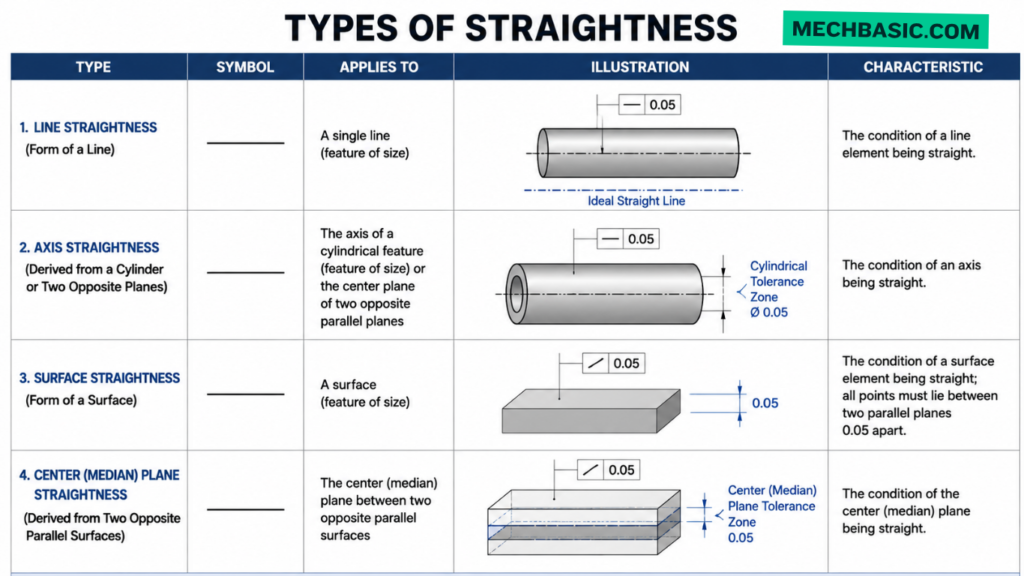
Straightness has two important applications:
Type 1 — Surface/line-element straightness
Controls the straightness of individual line elements on a surface.
Type 2 — Axis straightness
Controls the straightness of the derived median line/axis of a cylindrical feature of size.
These two applications are important because their tolerance zones are different.
5. Straightness of a Surface
When straightness is applied to a surface or line element, it controls each applicable line element independently.
For example:
| ⏤ | 0.05 |
may be applied to a surface.
The tolerance zone consists of two parallel lines separated by 0.05 mm for a line element in the specified direction.
The actual line element must remain between these two boundaries.
When straightness is applied to a surface, it controls:
Individual line elements of that surface.
It does not necessarily mean that the entire surface is flat.
This distinction is very important.
Example
A surface can have every individual line element within its straightness requirement while the overall surface still has variation in another direction.
Therefore:
Straightness ≠ Flatness
6. Straightness Applied to an Axis
Straightness can also control the axis of a cylindrical feature, such as:
- Shaft
- Hole
- Pin
- Cylindrical bore
For an axis, the tolerance zone is generally cylindrical.
Example:
| ⏤ | ⌀0.05 |
The diameter symbol ⌀ indicates a cylindrical tolerance zone.
The derived axis must remain inside a cylinder having:
Diameter = 0.05 mm
8. Example — Shaft Straightness
Suppose a shaft has:
Ø20.00 ± 0.05 mm
and its axis has:
Straightness | ⌀0.04 |
The shaft’s derived axis must remain within a cylindrical zone of:
Ø0.04 mm
along the applicable length of the shaft.
9. Straightness vs Flatness
This is one of the most common GD&T interview questions.
| Straightness | Flatness |
|---|---|
| Controls straightness | Controls flatness |
| Can apply to a line element or axis | Applies to a surface |
| Line element → two parallel lines | Two parallel planes |
| Axis → cylindrical tolerance zone | No cylindrical zone |
| Does not require datum | Does not require datum |
| Can control shaft axis | Controls entire surface |
Straightness = line
Flatness = surface
10. Straightness vs Circularity
Another common question:
| Straightness | Circularity |
|---|---|
| Controls straightness | Controls roundness |
| Controls a line/axis | Controls circular cross-section |
| Line/axis concept | Circular profile concept |
| Can control shaft axis | Controls each circular section |
| Tolerance zone can be two parallel lines or cylinder | Two concentric circles |
Straightness → Is it straight?
Circularity → Is it round?
11. Straightness vs Cylindricity
| Straightness | Cylindricity |
|---|---|
| Controls a line element or axis | Controls entire cylindrical surface |
| Narrower requirement | More comprehensive |
| Can control an axis | Controls cylindrical form |
| Does not by itself control roundness | Controls complete cylindrical form |
| Usually simpler to inspect | More demanding |
A cylindrical component can have a straight axis but still have poor cylindrical surface form.
12. Inspection of Straightness
Straightness can be inspected using different methods depending on the feature and required accuracy.
Common equipment includes:
- Surface plate
- Dial indicator
- Height gauge
- V-blocks
- Precision straightedge
- CMM
- Optical measuring systems
- Roundness/form measuring machines
Simple Shaft Inspection Method
For a shaft, one possible inspection setup is:
- Place the shaft appropriately on suitable supports.
- Rotate or translate it as required by the inspection method.
- Measure the deviation using a dial indicator.
- Compare the measured variation with the specified requirement.
- Ensure the measurement method matches the applicable GD&T standard and feature definition.
For precision inspection, a CMM or dedicated form-measuring machine may be used.
13. Common Mistakes
Mistake 1: Thinking straightness needs a datum
Incorrect.
Straightness is a form control and normally does not require a datum.
Mistake 2: Confusing straightness with flatness
Incorrect.
Straightness controls a line/axis; flatness controls a surface.
Mistake 3: Assuming straightness controls location
Straightness by itself does not establish the feature’s location.
A shaft can be perfectly straight but located away from its nominal position.
Mistake 4: Ignoring the diameter symbol
0.05 and ⌀0.05 indicate different tolerance-zone forms.
Always check whether the diameter symbol is present.
Mistake 5: Assuming shaft size tolerance automatically controls shaft straightness
Size tolerance controls size. It does not automatically impose the same requirement on geometric form.
14. Straightness — Interview Questions
Q1. What is straightness in GD&T?
Straightness is a form tolerance that controls the deviation of a line element or axis from perfect straightness.
Q2. What is the symbol for straightness?
⏤
Q3. Does straightness require a datum?
No.
Q4. What is the tolerance zone for surface straightness?
Two parallel lines for a line element, separated by the specified tolerance.
Q5. What is the tolerance zone for axis straightness?
A cylindrical tolerance zone when the straightness requirement is specified with the diameter symbol.
Q6. Is straightness a form tolerance?
Yes.
Q7. Can straightness be applied to a shaft?
Yes. It can control either applicable surface line elements or the derived axis, depending on how it is specified.
Q8. Can straightness control the location of a shaft?
No, not by itself.
Q9. What is the difference between straightness and flatness?
Straightness controls a line/axis, while flatness controls a surface.
Q10. Can straightness have MMC?
Yes, when applied to an applicable feature of size, subject to the governing GD&T standard.
Summary:
Straightness
- Category: Form
- Symbol: ⏤
- Datum required: No
- Basic purpose: Controls straightness
- Surface/line element zone: Two parallel lines
- Axis zone: Cylindrical when ⌀ is specified
- Controls location: No
- Controls orientation: Not by itself
- Can be applied to: Surfaces/line elements and applicable features of size
- MMC: Can be used in applicable feature-of-size applications
Straightness is a GD&T form control that limits how much a line element or derived axis may deviate from a theoretically perfect straight line.
Latest articles:

ANSI vs ISO Standards-Key Differences you need to know
Straightness-GD&T | GD&T Tutorials
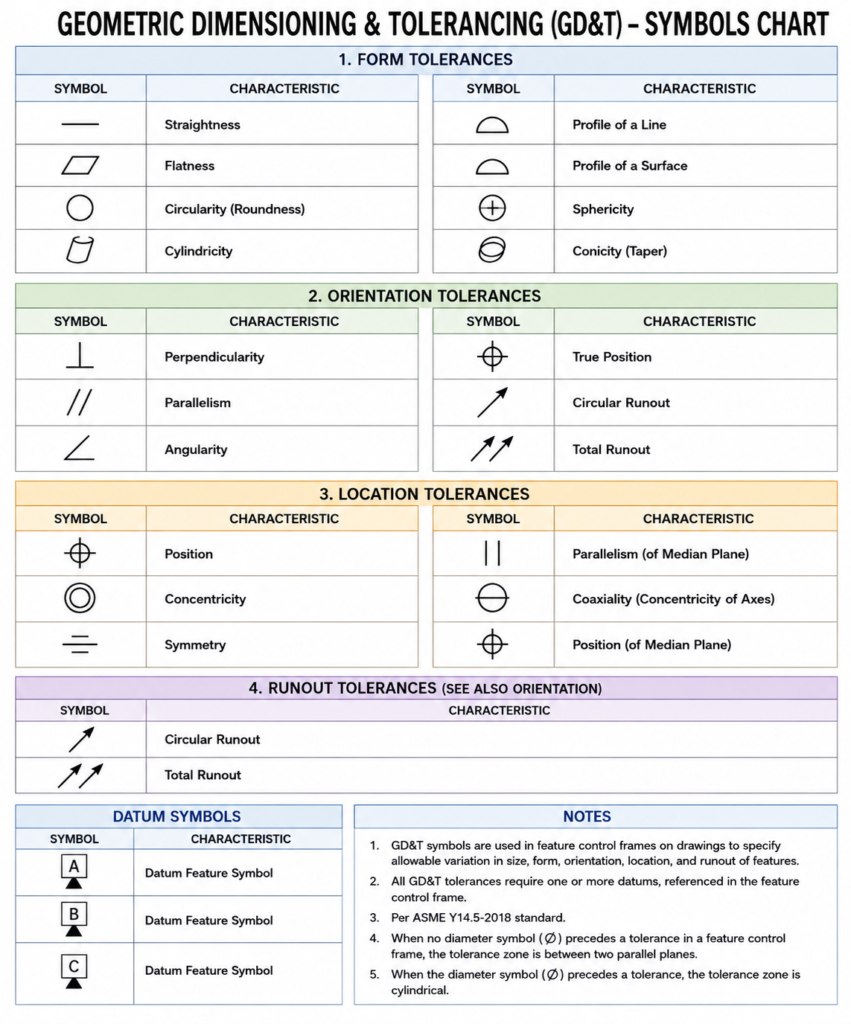
GD&T Symbols chart- Free download | GD&T
Geometric Dimensioning and Tolerancing (GD&T) is a standardized system used in engineering drawings to define…
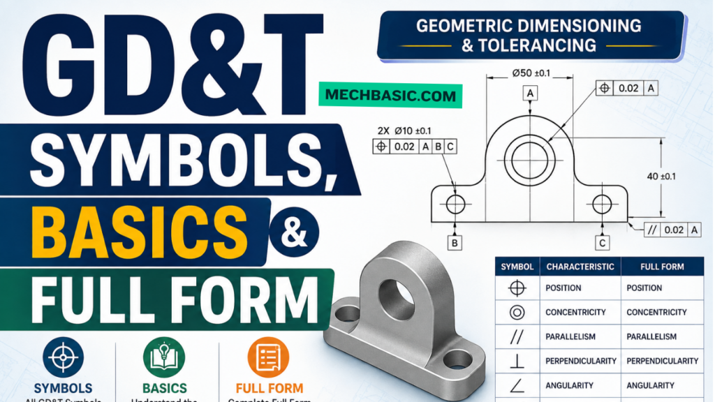
GD&T Symbols, Basics and full form
Can I convert a DXF to STL?
Can I convert a DXF to STL? Can I Convert a DXF to STL? Yes,…
Is DXF 2D or 3D?-Everything you need to know
Is DXF 2D or 3D? DXF (Drawing Exchange Format) supports both 2D and 3D data….
Related Tags:
Categories:




















