
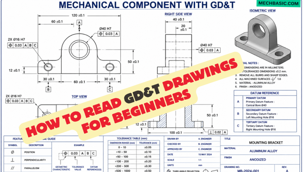
Overview:
How to Read a GD&T Drawing
1. Understand the Drawing
Review the views, dimensions, and overall geometry.
2. Read Dimensions
Identify nominal dimensions and their allowable limits.
3. Identify GD&T Symbols
Understand the geometric symbols used on the drawing.
4. Read Feature Control Frames
Check the tolerance value, modifiers, and datum references.
5. Identify Datums
Determine the primary, secondary, and tertiary datums.
6. Check Tolerance Zones
Identify the allowable geometric variation for each feature.
7. Apply the Datum Reference
Understand how the feature is positioned relative to the datums.
8. Verify the Feature
Compare the actual part with the specified GD&T requirements.
9. Follow the Drawing
Combine dimensions, tolerances, datums, and notes to understand the complete requirement.
In this article:
- How to Read a GD&T Drawing — Detailed Guide
- 1. Understand the Drawing
- 2. Read Dimensions
- 3. Identify GD&T Symbols
- 4. Read Feature Control Frames
- 5. Identify Datums
- 6. Understand the Datum Reference Frame
- 7. Check Tolerance Zones
- 8. Apply the Datum Reference
- 9. Determine What Feature Is Being Controlled
- 10. Determine Whether the Control Applies to a Surface or Axis
- 11. Check Material Condition Modifiers
- 12. Understand Bonus Tolerance
- 13. Look for Datum Feature Symbols
- 14. Check Drawing Notes
- 15. Understand Reference Dimensions
- 16. Read Hole Patterns
- 17. Understand Pattern Requirements
- 18. Check Profile Requirements
- 19. Check Runout Requirements
- Conclusion
How to Read a GD&T Drawing — Detailed Guide
Geometric Dimensioning and Tolerancing (GD&T) drawings can look complicated at first because they combine dimensions, symbols, datums, feature control frames, modifiers, and tolerance zones. However, once you follow a systematic method, reading a GD&T drawing becomes much easier.
Also read: 10 Golden Rules of reading GD&T
The key principle is:
Read the drawing from the overall part → dimensions → datums → Feature Control Frames → tolerance zones → inspection.
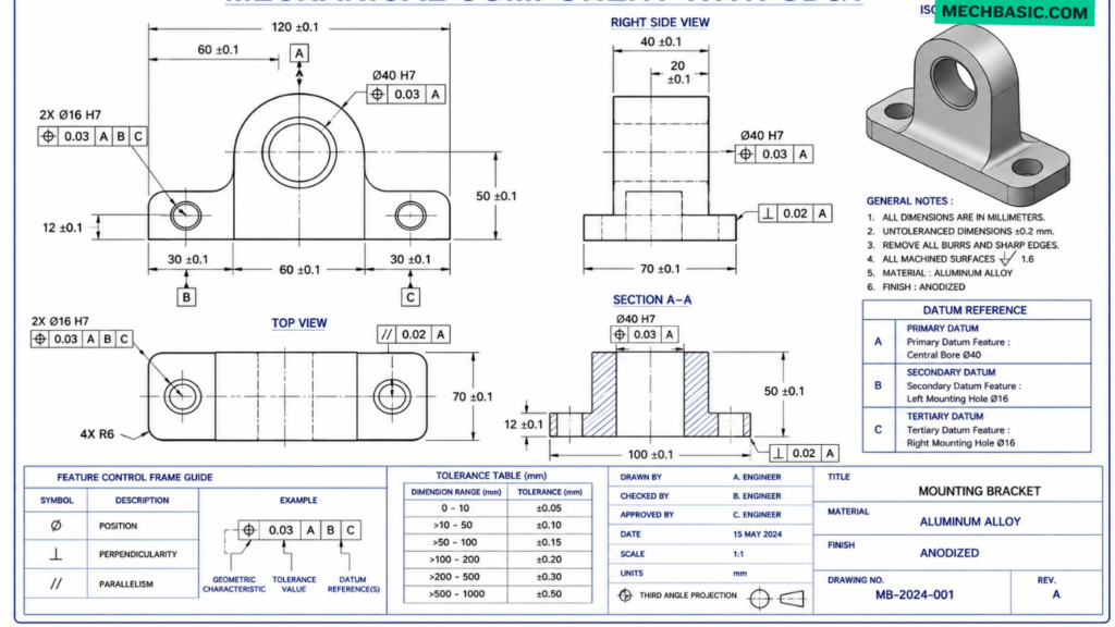
1. Understand the Drawing
Identify the Part
Before interpreting any GD&T requirement, first understand what the component is and what it does.
Look at:
- Part views
- Section views
- Detail views
- Title block
- Drawing notes
- Material specification
- Units
- Scale
- Revision information
2. Read Dimensions
Check Size
Next, identify the basic dimensional requirements.
Dimensions tell you about:
- Length
- Width
- Height
- Diameter
- Radius
- Thickness
- Hole size
- Feature spacing
Common Dimensional Tolerances
Bilateral Tolerance
Example:
50 ± 0.10 mm
Acceptable range:
49.90–50.10 mm
Unilateral Tolerance
Example:
20 +0.05 / 0 mm
Acceptable range:
20.00–20.05 mm
Limit Dimensions
Example:
49.90–50.10 mm
The upper and lower limits are directly specified.
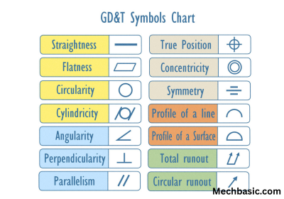
3. Identify GD&T Symbols
Common GD &T symbols include:
| Symbol/Control | Main Meaning |
|---|---|
| Straightness | Straight form |
| Flatness | Flat surface |
| Circularity | Roundness |
| Cylindricity | Cylindrical form |
| Parallelism | Parallel orientation |
| Perpendicularity | 90° orientation |
| Angularity | Specified angle |
| Position | Feature location |
| Profile | Shape/profile |
| Runout | Variation during rotation |
After understanding the dimensions, identify the GD&T symbols on the drawing.
The controls are generally divided into categories.
Form Controls
Control the shape of a feature:
- Straightness
- Flatness
- Circularity
- Cylindricity
Orientation Controls
Control feature orientation:
- Parallelism
- Perpendicularity
- Angularity
Location Controls
Control feature location:
- Position
- Concentricity
- Symmetry in traditional classifications
Profile Controls
Control:
- Profile of a line
- Profile of a surface
Runout Controls
Control rotational variation:
- Circular runout
- Total runout
4. Read Feature Control Frames
The Feature Control Frame (FCF) is one of the most important parts of a GD&T drawing.
It is normally divided into compartments.
A conceptual example is:
⌖ | ⌀0.10 | M | A | B | C
Read it from left to right.
First Box — Geometric Characteristic
The first compartment identifies the GD&T control.
⌖ | ⌀0.10 | M | A | B | C
For example:
⌖ means position.
Other examples include:
- ∥ → Parallelism
- ⊥ → Perpendicularity
- ⏥ → Flatness
- ○ → Circularity
Second Box — Tolerance
⌖ | ⌀0.10 | M | A | B | C
The next compartment gives the tolerance value.
Example:
0.10
means the specified geometric tolerance is 0.10, subject to the control and applicable standard.
If a diameter symbol appears:
⌀0.10
the tolerance zone is cylindrical.
Third Box — Modifier
⌖ | ⌀0.10 | M | A | B | C
A modifier may appear after the tolerance.
Common modifiers include:
MMC
Maximum Material Condition
LMC
Least Material Condition
RFS
Regardless of Feature Size
Understanding modifiers is particularly important for feature-of-size controls such as position.
Remaining Boxes — Datums
⌖ | ⌀0.10 | M | A | B | C
The remaining compartments identify the datum references.
Example:
⌖ | ⌀0.10 | M | A | B | C
can be interpreted conceptually as:
- Position control
- Cylindrical tolerance zone of 0.10
- MMC modifier
- Datum A
- Datum B
- Datum C
The exact interpretation must follow the applicable GD&T standard.
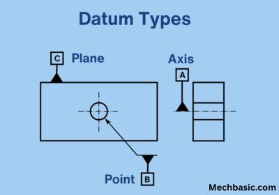
5. Identify Datums
Datums provide the reference framework for evaluating geometric requirements.
A drawing may identify:
Datum A
Primary reference
Datum B
Secondary reference
Datum C
Tertiary reference
Together they can establish a datum reference frame.
Also read: Why Datum planes are important?
6. Understand the Datum Reference Frame
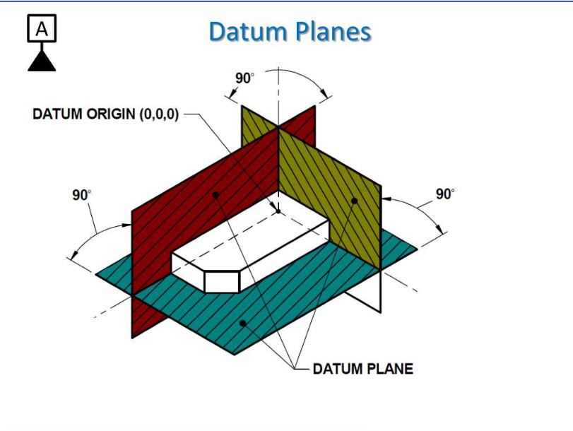
A common three-datum system can be understood conceptually using the 3-2-1 constraint principle.
Primary Datum
The primary datum establishes the main orientation and restricts the greatest number of degrees of freedom.
Secondary Datum
The secondary datum establishes additional orientation/location constraints.
Tertiary Datum
The tertiary datum completes the reference system.
7. Check Tolerance Zones
8. Apply the Datum Reference
Evaluate Orientation & Location
Once the datum system has been identified, determine how the feature is evaluated relative to it.
For example:
⊥ | 0.05 | A
means the controlled feature’s orientation is evaluated relative to Datum A.
Similarly:
∥ | 0.05 | A
means the feature is evaluated for parallel orientation relative to Datum A.
And:
⌖ | ⌀0.10 | A | B | C
uses the specified datum reference framework to establish the feature’s theoretical location and orientation requirements.
9. Determine What Feature Is Being Controlled
This is an important step.
The Feature Control Frame may be connected to a feature by:
- Leader line
- Extension line
- Dimension line
- Feature symbol
- A datum feature symbol
Determine exactly what the requirement applies to.
It could control:
- A surface
- A hole
- A shaft
- An axis
- A slot
- A pattern
- A curved surface
10. Determine Whether the Control Applies to a Surface or Axis
This is especially important for orientation controls.
Surface Control
A surface may be controlled using:
- Flatness
- Parallelism
- Perpendicularity
- Profile
Axis Control
A feature of size such as a hole or shaft may have its derived axis controlled using:
- Position
- Perpendicularity
- Parallelism
- Angularity
The tolerance-zone shape can differ depending on the feature being controlled.
11. Check Material Condition Modifiers
When you see a modifier in the Feature Control Frame, stop and interpret it carefully.
MMC
Maximum Material Condition
For a:
- Hole → smallest allowed size
- Shaft → largest allowed size
MMC can be particularly important for functional assembly requirements.
LMC
Least Material Condition
For a:
- Hole → largest allowed size
- Shaft → smallest allowed size
RFS
Regardless of Feature Size
The geometric tolerance applies independently of actual feature size, unless another applicable rule modifies that requirement.
12. Understand Bonus Tolerance
Suppose a hole has a position tolerance at MMC.
If the hole becomes larger than its MMC size, additional positional tolerance may become available under the applicable MMC rules.
This is known as:
Bonus Tolerance
Conceptually:
Actual departure from MMC = potential additional geometric tolerance
This is one reason why GD&T can provide more functional flexibility than simply using traditional ± coordinate tolerances.
13. Look for Datum Feature Symbols
Identify the Actual Datum Features
Do not confuse a datum feature with the datum itself.
For example:
A physical surface may be identified as a datum feature.
The theoretical plane derived from that feature is the datum.
Similarly:
A physical cylindrical feature can establish a datum axis.
This distinction becomes important during inspection.
14. Check Drawing Notes
A GD&T drawing may contain important information outside the Feature Control Frames.
Check:
- General tolerances
- Units
- Surface finish
- Material
- Heat treatment
- Deburring requirements
- Edge conditions
- Inspection requirements
- Reference dimensions
- Applicable standards
- Revision notes
A complete drawing interpretation requires considering all applicable drawing information.
15. Understand Reference Dimensions
What Is a Reference Dimension?
A reference dimension is generally provided for information rather than as an independently toleranced manufacturing requirement.
It may help communicate:
- Approximate size
- Calculated dimension
- Inspection information
- Relationship between features
Do not treat a reference dimension as an ordinary independently controlled dimension unless the drawing specifies otherwise.
16. Read Hole Patterns
Bolt-Hole Example
Suppose a drawing shows four holes around a rectangular pattern.
You may see:
- Hole diameter
- Basic dimensions locating the holes
- Position tolerance
- Datum references
For example:
Ø10
and:
⌖ | ⌀0.20 | A | B | C
The correct interpretation requires considering:
- Hole size
- Theoretically exact location
- Datum reference frame
- Positional tolerance zone
- Any material-condition modifier
17. Understand Pattern Requirements
Sometimes a GD&T requirement applies to a pattern of features rather than one feature independently.
For example:
Four holes may share one positional requirement.
This means you should determine whether the Feature Control Frame applies to:
- Each hole individually
- The entire pattern
- A common relationship among features
Pattern interpretation is particularly important in:
- Bolt circles
- Mounting holes
- Connector patterns
- Gear features
- Repeated slots
18. Check Profile Requirements
Profile is especially important when reading complex components.
A profile tolerance can control:
- Curved surfaces
- Irregular shapes
- Molded features
- Cast surfaces
- Aerodynamic surfaces
- CAD-defined geometry
A profile requirement should be interpreted together with:
- Basic dimensions
- Datum references
- Theoretically exact profile
- Tolerance value
19. Check Runout Requirements
For rotating components, look for:
Circular Runout
Controls variation at individual circular sections as the part rotates about a datum axis.
Total Runout
Controls variation over the entire indicated surface as the part rotates.
These are particularly relevant to:
- Shafts
- Rotors
- Wheels
- Bearing surfaces
- Rotating machine components
Conclusion
Reading a GD&T drawing is essentially the process of translating a two-dimensional engineering document into a three-dimensional functional requirement.
The correct approach is not to memorize every symbol independently. Instead, understand the relationship between:
Feature → Dimension → Datum → Feature Control Frame → Tolerance Zone → Inspection
Start by understanding the component and its function. Then read its dimensions and identify the datum features. Establish the datum reference frame, identify each Feature Control Frame, determine what feature it controls, and interpret the geometric tolerance, modifiers, and datum references.
Finally, determine how the actual manufactured feature will be measured and whether it satisfies the complete drawing requirement.
Simple Reading Formula
1. Identify the part
↓
2. Read dimensions
↓
3. Identify datums
↓
4. Read GD&T symbols
↓
5. Read Feature Control Frames
↓
6. Understand tolerance zones
↓
7. Apply datum references
↓
8. Check modifiers
↓
9. Inspect the feature
↓
10. Determine pass/fail
Latest articles:

Best Budget Workstation Laptops for SolidWorks and Heavy 3D Assembly Modeling
Best Budget Workstation Laptops for SolidWorks and Heavy 3D Assembly Modeling Overview What Does SOLIDWORKS…

SolidWorks Standard vs Professional vs Premium: Full Feature Comparison
SolidWorks Standard vs Professional vs Premium: Full Feature Comparison Overview: SOLIDWORKS Package Overview SOLIDWORKS comes…

SolidWorks 2026 License Cost: Perpetual vs Subscription Pricing Breakdown
SolidWorks 2026 License Cost: Perpetual vs Subscription Pricing Breakdown Overview: SOLIDWORKS 2026 License Options SOLIDWORKS…

Flatness-GD&T | GD&T Tutorials

ANSI vs ISO Standards-Key Differences you need to know

Straightness-GD&T | GD&T Tutorials
Related tags:
Categories:




















