
Key Takeaways
How to Make a Screw Thread in SOLIDWORKS
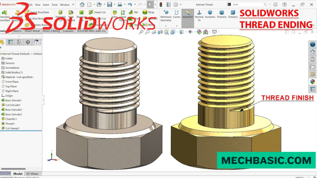
There are two common ways to create threads in SOLIDWORKS: Cosmetic Thread for drawings/documentation and Modeled Thread for actual 3D geometry.
Method 1: Thread Tool Recommended
- Create the Screw
- Start a new Part.
- Create the shaft using Extruded Boss/Base.
- Add the screw head if required.
- Select the Cylindrical Face
- Select the outside cylindrical surface where you want the thread.
- Go to Thread
- Select Insert → Features → Thread.
- Choose Thread Parameters
- Select the appropriate Thread Type/Standard.
- Choose the Size and Pitch.
- Select the required Thread Method and end condition.
- Set Thread Length
- Specify how long the threaded portion should be.
- Preview and Click OK
- SOLIDWORKS creates the helical thread geometry.
Method 2: Helix + Swept Cut
For more control over the thread profile:
Create Shaft → Create Helix → Sketch Thread Profile → Swept Cut
This method is useful when creating custom thread profiles or special screw geometries.
Cosmetic Thread
If you only need the thread to appear correctly in an engineering drawing without creating detailed 3D geometry:
Insert → Annotations → Cosmetic Thread
This keeps the model lightweight and is commonly preferred for large assemblies.
Example: M10 × 1.5 Thread
For an M10 × 1.5 external thread:
Cylinder Ø10 mm → Thread Tool → Metric → M10 × 1.5 → Set Thread Length → OK
Key Takeaway
Thread Tool → Standard → Size → Pitch → Length → OK
For manufacturing drawings: Cosmetic Thread
For realistic 3D models/3D printing: Modeled Thread
For custom threads: Helix + Swept Cut
In this article:
- How to Make a Screw Thread in SOLIDWORKS
- Method 1: Thread Tool Recommended
- Creating an Internal Thread
- Method 2: Helix + Swept Cut
- Example: M10 × 1.5 Thread
- Important: Thread Diameter and Pitch
- Modeled Thread vs Cosmetic Thread
- When Should You Use Each Method?
- Tips for Creating Threads
- Frequently Asked Questions (FAQs)
- Conclusion
How to Make a Screw Thread in SOLIDWORKS
Creating a screw thread in SOLIDWORKS can be done using several methods depending on whether you need a realistic thread for manufacturing, a lightweight cosmetic representation, or a fully modeled helical thread.
Two common methods are:
- Thread Tool — recommended for most applications
- Helix + Swept Cut — useful when you need greater control over the thread geometry
For a standard metric thread such as M10 × 1.5, the Thread Tool is usually the easiest approach.
SOLIDWORKS Help: Editing Cosmetic Threads: Official guide for applying lightweight 2D texture thread annotations to save graphical overhead in large assemblies.
Method 1: Thread Tool Recommended
The Thread feature is the quickest method for creating a modeled internal or external thread in SOLIDWORKS.
Step 1: Create a Cylindrical Part
Start a new part and create a cylinder.
For an external M10 thread, the nominal major diameter is:
10 mm
For example:
Sketch → Circle → Ø10 mm → Extruded Boss/Base
Step 2: Select the Cylindrical Face
Select the cylindrical face where you want to create the thread.
Then go to:
Insert → Features → Thread
Depending on your SOLIDWORKS version, the Thread feature can also be accessed from the appropriate Features tools.
Step 3: Select the Thread Type
In the Thread PropertyManager, select the appropriate:
Thread Type
For an M10 metric thread, choose the metric standard available in your installation.
Step 4: Select the Thread Size
Choose:
M10
Then select the required pitch.
For a standard coarse M10 thread:
M10 × 1.5
Where:
- M10 = nominal thread diameter of 10 mm
- 1.5 mm = thread pitch
Step 5: Set the Thread Length
Specify how far the thread should extend along the cylindrical surface.
For example:
Thread length = 25 mm
The actual length should match your design or manufacturing requirement.
Step 6: Choose the Thread Direction
Select the appropriate direction:
- Right-hand
- Left-hand
A standard screw thread is normally right-hand unless the design specifically requires a left-hand thread.
Step 7: Confirm the Feature
Click:
OK
SOLIDWORKS creates the modeled thread.
Your FeatureManager Design Tree will contain a Thread feature.
Creating an Internal Thread
The same Thread Tool can be used to create an internal thread.
Step 1
Create a hole with the appropriate diameter.
For example, an M10 × 1.5 tapped hole typically uses a tap-drill size around:
8.5 mm
for a conventional full thread, although the exact recommended drill size depends on the thread standard, tolerance class, material, and required percentage of thread.
Step 2
Select the cylindrical internal face.
Step 3
Use:
Thread → Metric → M10 × 1.5
Step 4
Set the required thread depth.
Step 5
Click OK.
Method 2: Helix + Swept Cut
The Helix + Swept Cut method gives you more control over the actual thread profile.
This method is useful when:
- You need a custom thread profile
- The standard Thread Tool does not provide the required geometry
- You need special thread dimensions
- You are modeling non-standard threads
- You want direct control over the helix
Step 1: Create the Cylinder
Create a cylindrical shaft.
For an example:
Diameter = 10 mm
Length = 30 mm
Step 2: Create a Helix
Select the appropriate circular face and create a sketch.
Go to:
Insert → Curve → Helix/Spiral
Set the required:
- Pitch
- Height
- Direction
- Start angle
For M10 × 1.5:
Pitch = 1.5 mm
Step 3: Create the Thread Profile
Create a sketch on a plane that intersects the beginning of the helix.
Draw the desired thread profile.
A simplified profile can be based on a triangular shape.
The exact profile should follow the applicable thread standard when the model is intended for manufacturing.
Step 4: Create a Swept Cut
Select:
Features → Swept Cut
Use:
Profile → Thread Profile
and:
Path → Helix
SOLIDWORKS cuts the profile along the helical path.
Step 5: Confirm the Feature
Click:
OK
The cylinder now contains a modeled helical thread.
Example: M10 × 1.5 Thread
Let’s create a basic external:
M10 × 1.5
thread.
Basic Specifications
| Parameter | Value |
|---|---|
| Nominal diameter | 10 mm |
| Pitch | 1.5 mm |
| Thread type | Metric |
| Typical direction | Right-hand |
| Example thread length | 20 mm |
Using the Thread Tool
Workflow
Create Cylinder
↓
Ø10 mm
↓
Select Cylindrical Face
↓
Thread
↓
Metric
↓
M10
↓
1.5 mm Pitch
↓
Set Thread Length
↓
OK
The resulting model contains a modeled M10 × 1.5 external thread.
Important: Thread Diameter and Pitch
A common mistake is to think that M10 × 1.5 means the thread is 10 mm deep.
It does not.
M10
The 10 represents the nominal diameter.
1.5
The 1.5 represents the axial distance between corresponding points on adjacent thread turns.
So:
M10 × 1.5
means:
10 mm nominal diameter + 1.5 mm pitch
Modeled Thread vs Cosmetic Thread
SOLIDWORKS also supports cosmetic thread representations.
Cosmetic Thread
A cosmetic thread represents the thread without modeling every helical surface.
Modeled Thread
A modeled thread physically creates the thread geometry.
| Feature | Cosmetic Thread | Modeled Thread |
|---|---|---|
| Lightweight | ⭐ | ❌ |
| Small file size | ⭐ | ❌ |
| Real geometry | ❌ | ⭐ |
| Manufacturing visualization | Good | Excellent |
| Rendering | Limited | ⭐ |
| Large assemblies | ⭐ | Can be heavy |
For large assemblies, cosmetic threads are often preferable because fully modeled threads can significantly increase model complexity.
When Should You Use Each Method?
Thread Tool
Use it when:
- The thread follows a standard
- You need a quick modeled thread
- You are designing normal fasteners
- You need internal or external threads
- You want a simpler workflow
Helix + Swept Cut
Use it when:
- The thread is non-standard
- You need a custom profile
- You need precise control over the helical geometry
- You are designing specialized components
Tips for Creating Threads
1. Use the Correct Thread Standard
Select the appropriate standard, such as:
- Metric
- ANSI Inch
- Other supported standards
2. Verify the Pitch
Always confirm that the pitch matches the required fastener or tapped hole.
3. Add a Lead-In
For a realistic manufactured thread, consider adding an appropriate chamfer or lead-in at the thread entrance.
4. Avoid Unnecessary Modeled Threads
Thousands of detailed threads can make an assembly slow.
Use cosmetic representations when physical thread geometry isn’t necessary.
5. Check Manufacturing Requirements
For a production component, use the applicable engineering standard and specify the required:
- Thread size
- Pitch
- Tolerance class
- Thread depth
- Thread length
- Internal/external designation
Frequently Asked Questions (FAQs)
1. What is the easiest way to create a screw thread in SOLIDWORKS?
The Thread Tool is generally the easiest method for standard internal and external threads.
2. How do I create an M10 × 1.5 thread?
Select the cylindrical face, activate the Thread feature, select the metric thread standard, choose M10, and specify 1.5 mm pitch.
3. Can I create an internal thread?
Yes. The Thread Tool can create internal threads on cylindrical hole surfaces.
4. Can I create a custom thread?
Yes. A Helix + Swept Cut workflow provides greater control over custom thread geometry.
5. Should I model every thread in an assembly?
Usually not. Fully modeled threads can increase rebuild time and file size. For many assemblies, cosmetic threads are more efficient.
Conclusion
There are two main ways to make a screw thread in SOLIDWORKS.
Method 1 — Thread Tool Recommended
Cylinder → Select Face → Thread → Select Standard → M10 × 1.5 → Set Length → OK
This is the best choice for most standard threads.
Method 2 — Helix + Swept Cut
Cylinder → Helix → Create Thread Profile → Swept Cut
This method is better when you need a custom or non-standard thread profile.
For the common M10 × 1.5 thread, the Thread Tool provides the simplest and most efficient workflow.
Latest articles:

SolidWorks Standard vs Professional vs Premium: Full Feature Comparison
SolidWorks Standard vs Professional vs Premium: Full Feature Comparison Overview: SOLIDWORKS Package Overview SOLIDWORKS comes…

SolidWorks 2026 License Cost: Perpetual vs Subscription Pricing Breakdown
SolidWorks 2026 License Cost: Perpetual vs Subscription Pricing Breakdown Overview: SOLIDWORKS 2026 License Options SOLIDWORKS…

Flatness-GD&T | GD&T Tutorials

ANSI vs ISO Standards-Key Differences you need to know

Straightness-GD&T | GD&T Tutorials
GD&T Symbols chart- Free download | GD&T
Geometric Dimensioning and Tolerancing (GD&T) is a standardized system used in engineering drawings to define…
Categories:




















