
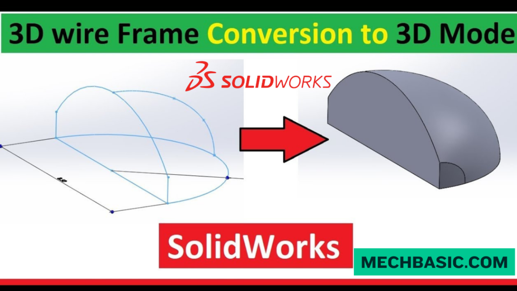
Key Takeaways:
SOLIDWORKS: Transition from Wireframe to Solid Body
What is Wireframe Modeling?
Wireframe modeling represents an object using points, lines, curves, and edges without defining a surface or volume. It is mainly used to establish the basic geometry and shape of a model.
What is a Solid Body?
A solid body is a fully enclosed 3D model that contains faces, edges, and volume. Solid bodies can be used for mass-property calculations, assemblies, drawings, simulation, and manufacturing.
How to Convert Wireframe to Solid Body:
A wireframe can be converted into a solid by creating closed profiles, generating surfaces or sketches, and then using solid features such as Extruded Boss/Base, Revolved Boss/Base, Swept Boss/Base, or Boundary/Lofted features.
Typical Workflow:
Wireframe → Closed Sketch/Profile → Surface or Solid Feature → Trim/Join → Solid Body
Key Takeaway
Wireframe = Lines & Curves
Surface = Faces without Volume
Solid Body = Enclosed Volume → Ready for Design, Simulation & Manufacturing
In this article:
- SOLIDWORKS: Transition from Wireframe to Solid Body
- What is Wireframe Modeling?
- What is a Solid Body?
- How to Convert Wireframe to Solid Body
- Method 2: Use Several Profiles with Loft
- Method 3: Use Boundary Features
- Method 4: Create Surfaces and Knit Them
- Method 5: Use Sweep
- Method 6: Use Revolve
- Typical Workflow
- Wireframe vs. Solid Body
- Important: The Wireframe Must Be Suitable
- Conclusion
SOLIDWORKS: Transition from Wireframe to Solid Body
Introduction
In SOLIDWORKS, wireframe modeling represents geometry using lines, curves, and edges, while a solid body represents a complete 3D object with volume.
Converting wireframe information into a solid model is useful when working with imported CAD data, legacy designs, or geometry created from sketches and curves.
What is Wireframe Modeling?
Wireframe modeling represents a 3D object using:
- Lines
- Arcs
- Curves
- Splines
- Sketch entities
- Reference geometry
A wireframe does not have enclosed faces or physical volume.
For example, a simple wireframe box may contain only its twelve edges:
       ______
      /     /|
     /_____/ |
     |     | |
     |     | /
     |_____|/
The lines define the shape, but the object does not yet have a solid interior.
Common Uses
Wireframe geometry can be useful for:
- Conceptual layouts
- Reference geometry
- Complex curves
- Imported CAD data
- Creating profiles for surface/solid features
What is a Solid Body?
A solid body is a complete 3D object containing:
- Faces
- Edges
- Vertices
- Enclosed volume
For example, an extruded rectangle becomes a solid block.
Solid bodies can be used for:
- Fillets
- Chamfers
- Shells
- Hole features
- Boolean operations
- Mass properties
- Assemblies
- Manufacturing drawings
A solid model can therefore represent the actual physical form of a manufactured component.
How to Convert Wireframe to Solid Body
There is not one universal “Convert Wireframe to Solid” command in SOLIDWORKS. The correct method depends on what type of wireframe geometry you have.
Method 1: Use a Closed Sketch + Extrude
This is the simplest method when the wireframe consists of a closed 2D profile.
Steps
- Create or open the sketch.
- Make sure the profile is completely closed.
- Exit the sketch.
- Select Features → Extruded Boss/Base.
- Enter the extrusion depth.
- Click OK.
Example
Closed Rectangle
↓
Extruded Boss/Base
↓
Solid Block
This is the most common approach for basic wireframe-to-solid modeling.
Method 2: Use Several Profiles with Loft
For more complex wireframe geometry, you can create solid geometry between multiple closed profiles.
Workflow
Profile 1
↓
Profile 2
↓
Profile 3
↓
Lofted Boss/Base
↓
Solid Body
This method is useful for:
- Organic shapes
- Transition components
- Product housings
- Complex mechanical forms
Method 3: Use Boundary Features
When multiple curves define a complex shape, the Boundary Boss/Base feature can create a solid between suitable profiles and directions.
This is useful for more controlled shapes than a simple extrusion.
Typical applications include:
- Complex housings
- Industrial components
- Product surfaces
- Aerodynamic forms
Method 4: Create Surfaces and Knit Them
If the wireframe defines a complex 3D shape rather than a simple closed sketch, a surface-based workflow may be more appropriate.
Workflow
Wireframe Curves
↓
Create Surfaces
↓
Knit Surfaces
↓
Create Solid
SOLIDWORKS provides surface tools such as:
- Extruded Surface
- Revolved Surface
- Swept Surface
- Lofted Surface
- Boundary Surface
- Knit Surface
After creating and knitting the surfaces into a closed volume, you can use the option to Create solid where applicable.
Method 5: Use Sweep
If the wireframe contains a path and profile, a Sweep can create a solid body.
This is useful for:
- Pipes
- Tubes
- Handles
- Cables
- Structural members
Method 6: Use Revolve
If the wireframe contains a suitable profile and centerline, you can create a rotational solid.
Workflow
Closed Profile
↓
Centerline
↓
Revolved Boss/Base
↓
Solid Body
Common applications include:
- Shafts
- Bushings
- Pulleys
- Cylindrical components
- Rotational parts
Typical Workflow
A general wireframe-to-solid workflow can be summarized as:
Step 1: Import or Create Wireframe
Create the required:
- Lines
- Arcs
- Curves
- Splines
Step 2: Check the Geometry
Make sure the curves connect correctly.
Look for:
- Gaps
- Overlapping entities
- Open profiles
- Incorrect endpoints
Step 3: Create Closed Profiles
Where required, convert the wireframe into closed sketch profiles.
Step 4: Choose the Appropriate Solid Feature
Depending on the geometry, use:
- Extrude
- Revolve
- Sweep
- Loft
- Boundary
- Surface + Knit
Step 5: Verify the Solid
Check the FeatureManager Design Tree for the resulting Solid Bodies folder.
You can also use:
Evaluate → Check
to identify geometry problems.
Step 6: Add Manufacturing Features
Once the solid exists, add:
- Fillets
- Chamfers
- Holes
- Cuts
- Shells
- Patterns
Wireframe vs. Solid Body
| Feature | Wireframe | Solid Body |
|---|---|---|
| Lines/curves | ✅ | ✅ |
| Faces | ❌ | ✅ |
| Enclosed volume | ❌ | ✅ |
| Mass properties | ❌ | ✅ |
| Fillets | ❌ | ✅ |
| Chamfers | ❌ | ✅ |
| Hole features | ❌ | ✅ |
| Boolean operations | Limited | ✅ |
| Manufacturing model | Limited | ✅ |
| 3D physical representation | ❌ | ✅ |
Important: The Wireframe Must Be Suitable
A common reason a solid feature fails is that the wireframe is not a closed profile.
For example:
Closed profile:
┌────────┐
│        │
└────────┘
can usually be extruded.
But:
┌────────
│
└────────
contains an open gap and cannot directly create a conventional solid from that sketch.
Check for:
- Small gaps
- Unconnected endpoints
- Duplicate lines
- Self-intersecting curves
- Incorrect geometry
Quick Fix
If you have wireframe geometry and want a solid as quickly as possible:
1. Edit the sketch
↓
2. Make sure the profile is closed
↓
3. Exit Sketch
↓
4. Select Features → Extruded Boss/Base
↓
5. Enter depth
↓
6. Click ✔ OK
If the geometry is truly 3D and cannot be represented by a simple extrusion, consider Sweep, Loft, Boundary, or Surface + Knit instead.
Conclusion
Transitioning from wireframe to solid modeling in SOLIDWORKS depends on the structure of your geometry.
The key is to choose the modeling feature that matches the geometry rather than trying to force every wireframe into a simple extrusion.
Latest articles:

Flatness-GD&T | GD&T Tutorials

ANSI vs ISO Standards-Key Differences you need to know

Straightness-GD&T | GD&T Tutorials
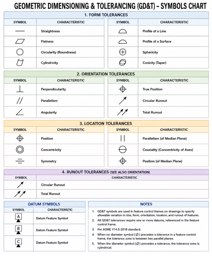
GD&T Symbols chart- Free download | GD&T
Geometric Dimensioning and Tolerancing (GD&T) is a standardized system used in engineering drawings to define…
GD&T Symbols, Basics and full form

Can I convert a DXF to STL?
Can I convert a DXF to STL? Can I Convert a DXF to STL? Yes,…
Related Tags:
Categories:




















