
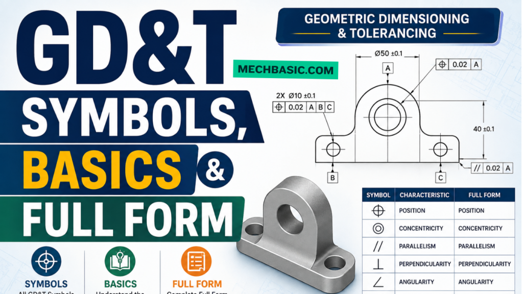
Overview:
GD&T Symbols, Basics & Full Form
What is GD&T?
GD&T = Geometric Dimensioning & Tolerancing
- A standard language used on engineering drawings
- Defines the allowable variation in a part
- Controls form, orientation, location & runout
- Helps achieve accurate fit, function & interchangeability
Why is GD&T Important?
- Reduces manufacturing ambiguity
- Improves part quality and consistency
- Simplifies inspection and measurement
- Supports better communication between Design → Manufacturing → Quality
Let’s understand GD&T — symbol by symbol.
In this article:
- GD&T Symbols, Basics, and Full Forms
- 1. GD&T Full Form
- 2. Why Is GD&T Used?
- 3. Basic Concepts of GD&T
- 4. The Three Major Categories of GD&T
- 5. Complete GD&T Symbol Chart
- 6. Form Tolerances
- 7. Profile Tolerances
- 9. Orientation Tolerances
- 10. Location Tolerances
- 11. Symmetry
- 12. Runout Tolerances
- 13. GD&T Feature Control Frame
- 14. Datum Reference System
- 15. Material Condition Modifiers
- 16. Tolerance Zone
- 17. GD&T vs Traditional ± Tolerancing
- 18. GD&T Symbol Categories — Easy Memory Trick
- 32. Frequently Asked Questions (FAQ)
- Conclusion
GD&T Symbols, Basics, and Full Forms
GD&T stands for Geometric Dimensioning and Tolerancing. It is a standardized engineering drawing language used to define the size, form, orientation, location, and allowable variation of a component’s features.
Unlike conventional ± tolerancing, GD&T uses symbols and rules to communicate design requirements accurately.
It is widely used in mechanical engineering, manufacturing, CNC machining, automotive, aerospace, inspection, and quality control.
1. GD&T Full Form
GD&T = Geometric Dimensioning and Tolerancing
| Term | Meaning |
|---|---|
| Geometric | Relates to the geometry/form of a feature |
| Dimensioning | Specifies the required size and location |
| Tolerancing | Specifies the permissible variation |
GD&T is commonly based on standards such as ASME Y14.5 in the United States and ISO GPS standards internationally.
2. Why Is GD&T Used?
GD&T provides a precise method of communicating design requirements between:
Designer → Manufacturer → Inspector → Quality Department
Major advantages
- Improves drawing clarity
- Controls manufacturing variation
- Ensures proper assembly
- Reduces unnecessary tight tolerances
- Improves interchangeability
- Reduces manufacturing cost
- Makes inspection easier
- Provides a common engineering language
3. Basic Concepts of GD&T
Before learning the symbols, it is important to understand a few fundamental terms.
3.1 Feature
A feature is a physical portion of a component that can be identified on a drawing.
Examples:
- Hole
- Shaft
- Slot
- Surface
- Cylinder
- Step
- Plane
3.2 Feature of Size
A feature that has a measurable size, generally associated with:
- Diameter
- Width
- Thickness
- Length
Examples:
- Hole diameter
- Shaft diameter
- Slot width
3.3 Datum
A datum is a theoretically exact reference from which another feature is located or oriented.
Datums are usually identified by letters such as:
A, B, C
For example:
- Datum A = primary reference surface
- Datum B = secondary reference
- Datum C = tertiary reference
A datum system can therefore establish the component’s reference coordinate system.
4. The Three Major Categories of GD&T
GD&T controls can broadly be divided into:
A. Form
Controls the shape of an individual feature.
B. Orientation
Controls the angular relationship between features.
C. Location
Controls where a feature is located.
There is also profile and runout, which provide additional geometric controls.
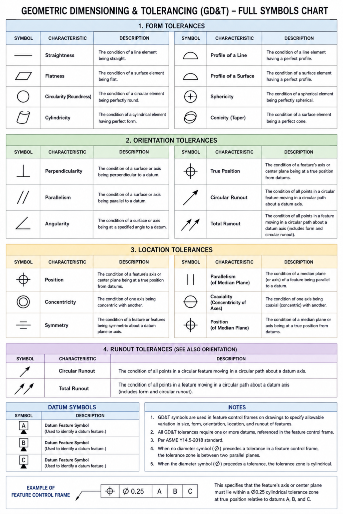
5. Complete GD&T Symbol Chart
The following are the major GD&T symbols used in engineering drawings.
| Category | Control | Symbol | What it controls |
|---|---|---|---|
| Form | Straightness | ⏤ | Straightness of a line/axis |
| Flatness | ▱ | Flatness of a surface | |
| Circularity / Roundness | ○ | Roundness of a circular feature | |
| Cylindricity | ⌭ | Entire cylindrical form | |
| Profile | Profile of a Line | ⌒ | Profile of a line |
| Profile of a Surface | ⌓ | Profile of a surface | |
| Orientation | Angularity | ∠ | Angular orientation |
| Perpendicularity | ⟂ | 90° orientation | |
| Parallelism | ∥ | Parallel orientation | |
| Location | Position | ⌖ | Exact location of a feature |
| Concentricity* | ◎ | Relationship of median points/axes | |
| Symmetry* | ⌯ | Symmetry about a datum | |
| Runout | Circular Runout | ↗ | Circular variation during rotation |
| Total Runout | ⌰ | Entire surface variation |
*Concentricity and symmetry are retained in some standards/drawing practices but are no longer included as active controls in current ASME Y14.5 practice; position and other controls are generally preferred where applicable.
Note: Symbol appearance can vary slightly depending on font, CAD software, standard, and drawing convention.
6. Form Tolerances
Form tolerances control the shape of an individual feature. They generally do not require a datum reference.
There are four principal form controls:
- Straightness
- Flatness
- Circularity
- Cylindricity
Straightness
Symbol: ⏤
Straightness controls how much a line or axis may deviate from a theoretically perfect straight line.
Example
A shaft may be specified as:
Straightness | 0.05 mm
This means the controlled line element must remain within the specified straightness tolerance zone.
Applications
- Shafts
- Edges
- Centerlines
- Guide rails
Important point
Straightness does not control:
- Parallelism
- Perpendicularity
- Location
It controls only straightness.
Flatness
Symbol: ▱
Flatness controls how much a surface can deviate from a theoretically perfect plane.
A flatness tolerance creates two parallel planes separated by the specified tolerance.
Example
Flatness | 0.03 mm
The entire controlled surface must lie between two parallel planes separated by 0.03 mm.
Applications
- Mounting surfaces
- Gasket surfaces
- Machine bases
- Flanges
Important point
Flatness does not require a datum.
Circularity / Roundness
Symbol: ○
Circularity controls the roundness of individual circular cross-sections.
The actual circular profile must lie between two concentric circles separated radially by the specified tolerance.
Example
Circularity | 0.02 mm
This means each applicable cross-section must meet the specified roundness requirement.
Applications
- Shafts
- Bearings
- Holes
- Cylindrical components
Important point
Circularity does not directly control:
- Axis location
- Orientation
- Cylindricity
Cylindricity
Symbol: ⌭
Cylindricity controls the complete cylindrical form of a surface.
It simultaneously controls the surface’s:
- Roundness
- Straightness
- Cylindrical form
Example
Cylindricity | 0.05 mm
The entire cylindrical surface must lie between two coaxial cylinders separated by 0.05 mm.
Applications
- Precision shafts
- Hydraulic cylinders
- Bearing seats
- Rotating components
Difference between circularity and cylindricity
| Circularity | Cylindricity |
|---|---|
| Controls individual cross-sections | Controls the entire cylindrical surface |
| 2D control | 3D control |
| No datum | No datum |
| Usually simpler | More comprehensive |
7. Profile Tolerances
Profile controls are useful for controlling complex curves and surfaces.
There are two main profile controls:
- Profile of a line
- Profile of a surface
Profile of a Line
Symbol: ⌒
Profile of a line controls the shape of a line element or cross-sectional profile.
It is particularly useful for:
- Curved surfaces
- Radii
- Contoured sections
- Airfoil profiles
Profile of a Surface
Symbol: ⌓
Profile of a surface controls the entire three-dimensional surface.
It can control:
- Form
- Orientation
- Location
depending on how the tolerance is referenced and applied.
Applications
- Cast components
- Forged components
- Automotive body panels
- Complex machined surfaces
- Molded parts
9. Orientation Tolerances
Orientation controls the angular relationship of a feature relative to a datum.
The major orientation controls are:
- Parallelism
- Perpendicularity
- Angularity
Parallelism
Symbol: ∥
Parallelism controls how parallel a surface, line, or axis is to a datum.
Example
Parallelism | 0.04 | A
This means the controlled feature must maintain the specified parallel relationship with datum A.
Applications
- Parallel faces
- Shafts
- Guide surfaces
- Machine slides
Important
Parallelism controls orientation, not necessarily the feature’s location.
Perpendicularity
Symbol: ⟂
Perpendicularity controls whether a feature is oriented at 90° to a datum.
Example
Perpendicularity | 0.03 | A
The controlled feature must remain within the specified perpendicularity tolerance zone relative to datum A.
Applications
- Holes
- Shafts
- Mounting faces
- Vertical walls
Angularity
Symbol: ∠
Angularity controls a feature at a specified angle other than the standard 0° or 90° relationships.
For example:
30° ± 0.5°
may define a basic angle, while GD&T angularity controls the allowable geometric variation around that theoretically exact angle.
Applications
- Tapered surfaces
- Inclined holes
- Angled faces
- Chamfers
10. Location Tolerances
Location controls specify where a feature should be positioned.
The most important modern location control is:
Position
Symbol: ⌖
Position is one of the most widely used GD&T controls.
It controls the location of a feature relative to one or more datums.
Position Tolerance
Suppose a drawing specifies:
⌀0.10 | A | B | C
for a hole.
The position tolerance establishes a cylindrical tolerance zone around the theoretically exact position of the hole axis.
This controls the hole’s location and, depending on the application, can also establish orientation requirements.
Why position is important
Instead of specifying separate X and Y ± tolerances, position can define a more functional tolerance zone.
Common applications
- Bolt holes
- Mounting holes
- Pin holes
- Hole patterns
- Shafts
- Slots
Concentricity
Symbol: ◎
Concentricity controls the relationship between the median points of a feature and a datum axis.
It is a highly specialized control and can be difficult to inspect.
In many practical applications, position or runout is preferred because they often provide a more functional way of controlling rotational features.
11. Symmetry
Symbol: ⌯
Symmetry controls whether the median plane or median points of a feature are symmetrically located about a datum plane.
Like concentricity, symmetry is relatively uncommon in modern practical GD&T applications and may be replaced by more functional controls such as position or profile.
12. Runout Tolerances
Runout is generally used for rotating components.
There are two main types:
- Circular runout
- Total runout
Circular Runout
Symbol: ↗
Circular runout controls variation at individual circular sections as the part is rotated about a datum axis.
It can control variation caused by combinations of:
- Roundness
- Coaxiality/orientation effects
Applications
- Shafts
- Rotors
- Bearing surfaces
- Wheels
- Pulleys
Total Runout
Symbol: ⌰
Total runout controls variation over the entire surface while the part is rotated around its datum axis.
It is more comprehensive than circular runout.
Example applications
- Precision shafts
- Rotating seals
- Bearing journals
- Spindles
13. GD&T Feature Control Frame
A Feature Control Frame (FCF) is the rectangular box used to specify a geometric tolerance.
A simplified example is:
| ⌖ | ⌀0.10 | A | B | C |
It can be understood as:
| Section | Meaning |
|---|---|
| ⌖ | Geometric characteristic |
| ⌀0.10 | Tolerance zone |
| A | Primary datum |
| B | Secondary datum |
| C | Tertiary datum |
14. Datum Reference System
A datum reference system normally consists of:
Primary Datum — A
Establishes the first reference.
Secondary Datum — B
Establishes the second reference.
Tertiary Datum — C
Establishes the final reference.
A useful way to visualize it is:
A → B → C
This establishes the part’s coordinate reference for inspection and manufacturing.
15. Material Condition Modifiers
One of the most important GD&T concepts is material condition.
Common symbols include:
MMC — Maximum Material Condition
Symbol: Ⓜ
MMC represents the condition where a feature contains the maximum amount of material.
For a hole, MMC corresponds to the smallest allowable hole.
For a shaft, MMC corresponds to the largest allowable shaft.
LMC — Least Material Condition
Symbol: Ⓛ
LMC represents the condition where a feature contains the least amount of material.
For a hole, this is the largest allowable hole.
For a shaft, this is the smallest allowable shaft.
RFS — Regardless of Feature Size
Symbol: none
RFS means the geometric tolerance applies regardless of the actual size of the feature.
RFS is generally the default condition unless another material-condition modifier is specified by the applicable standard.
16. Tolerance Zone
A tolerance zone is the region within which the actual feature must lie.
Examples:
Straightness
Two parallel lines or planes.
Flatness
Two parallel planes.
Position
Usually a cylindrical zone for a cylindrical feature.
Circularity
Two concentric circles.
Understanding the shape of the tolerance zone is essential for interpreting GD&T.
17. GD&T vs Traditional ± Tolerancing
| Traditional Tolerancing | GD&T |
|---|---|
| Uses mostly ± dimensions | Uses geometric symbols |
| Can require many dimensions | Often communicates requirements more clearly |
| Less direct functional definition | Strong functional relationship |
| Can lead to unnecessarily tight tolerances | Can allow appropriate manufacturing variation |
| Limited control of form/orientation | Controls form, orientation, location, profile and runout |
| Inspection can be less structured | Works well with CMM inspection |
18. GD&T Symbol Categories — Easy Memory Trick
You can remember the major controls as:
F-O-L-P-R
F — Form
- Straightness
- Flatness
- Circularity
- Cylindricity
O — Orientation
- Parallelism
- Perpendicularity
- Angularity
L — Location
- Position
- Concentricity*
- Symmetry*
P — Profile
- Profile of a line
- Profile of a surface
R — Runout
- Circular runout
- Total runout
This is a useful structure for interviews and examinations.
32. Frequently Asked Questions (FAQ)
Q1. What is the full form of GD&T?
GD&T = Geometric Dimensioning and Tolerancing.
Q2. What is the main purpose of GD&T?
To communicate the required geometrical accuracy and allowable variation of manufactured components clearly and functionally.
Q3. How many major types of GD&T controls are there?
The controls are commonly grouped into:
- Form
- Profile
- Orientation
- Location
- Runout
Q4. Which GD&T controls do not require a datum?
The four form controls generally do not require a datum:
- Straightness
- Flatness
- Circularity
- Cylindricity
Q5. Which GD&T symbol is most commonly used for hole location?
Position (⌖) is commonly used to control the location of holes.
Q6. What is a datum?
A datum is a theoretically exact reference used to establish the location and/or orientation of other features.
Q7. What does MMC mean?
MMC = Maximum Material Condition.
For a hole, MMC is the smallest hole size.
For a shaft, MMC is the largest shaft size.
Q8. What does LMC mean?
LMC = Least Material Condition.
For a hole, LMC is the largest hole size.
For a shaft, LMC is the smallest shaft size.
Q9. What is RFS?
RFS = Regardless of Feature Size.
It means the geometric tolerance applies independently of the actual feature size, unless another condition is specified.
Q10. What is the difference between flatness and parallelism?
Flatness controls a surface by itself.
Parallelism controls the orientation of a feature relative to a datum.
Q11. What is the difference between circularity and cylindricity?
Circularity controls individual circular cross-sections.
Cylindricity controls the complete cylindrical surface.
Q12. What is the difference between perpendicularity and angularity?
Perpendicularity controls a 90° relationship.
Angularity controls a specified angle other than the standard perpendicular relationship.
Q13. What is a Feature Control Frame?
It is the rectangular box on a drawing that contains the:
- Geometric characteristic symbol
- Tolerance value
- Datum references
- Applicable modifiers
Q14. Does flatness require a datum?
No. Flatness is a form control and normally controls the surface without reference to a datum.
Q15. Why is GD&T important in CNC machining?
GD&T helps define the functional requirements of machined components so that manufacturers know how much variation is acceptable while still ensuring proper assembly and operation.
Conclusion
GD&T (Geometric Dimensioning and Tolerancing) is a standardized engineering language used to control the form, orientation, location, profile, and runout of component features.
Also Read: Purpose and rules of GD&T
The most important concepts to understand are:
- Form: Straightness, flatness, circularity, cylindricity
- Profile: Profile of line and surface
- Orientation: Parallelism, perpendicularity, angularity
- Location: Position, plus specialized controls such as concentricity and symmetry
- Runout: Circular and total runout
- Datums: Establish the reference system
- Feature Control Frame: Communicates the geometric requirement
- MMC/LMC/RFS: Define material-condition relationships
For a beginner, the best learning sequence is:
GD&T basics → Symbols → Datums → Feature Control Frames → Tolerance zones → MMC/LMC/RFS → Position → Advanced applications → Drawing interpretation.
Mastering these concepts is especially useful for mechanical design, production engineering, CNC machining, metrology, CMM inspection, quality control, and engineering interviews.
Latest articles:

Best Budget Workstation Laptops for SolidWorks and Heavy 3D Assembly Modeling
Best Budget Workstation Laptops for SolidWorks and Heavy 3D Assembly Modeling Overview What Does SOLIDWORKS…

SolidWorks Standard vs Professional vs Premium: Full Feature Comparison
SolidWorks Standard vs Professional vs Premium: Full Feature Comparison Overview: SOLIDWORKS Package Overview SOLIDWORKS comes…

SolidWorks 2026 License Cost: Perpetual vs Subscription Pricing Breakdown
SolidWorks 2026 License Cost: Perpetual vs Subscription Pricing Breakdown Overview: SOLIDWORKS 2026 License Options SOLIDWORKS…

Flatness-GD&T | GD&T Tutorials

ANSI vs ISO Standards-Key Differences you need to know

Straightness-GD&T | GD&T Tutorials
Related Tags:
Categories:




















