
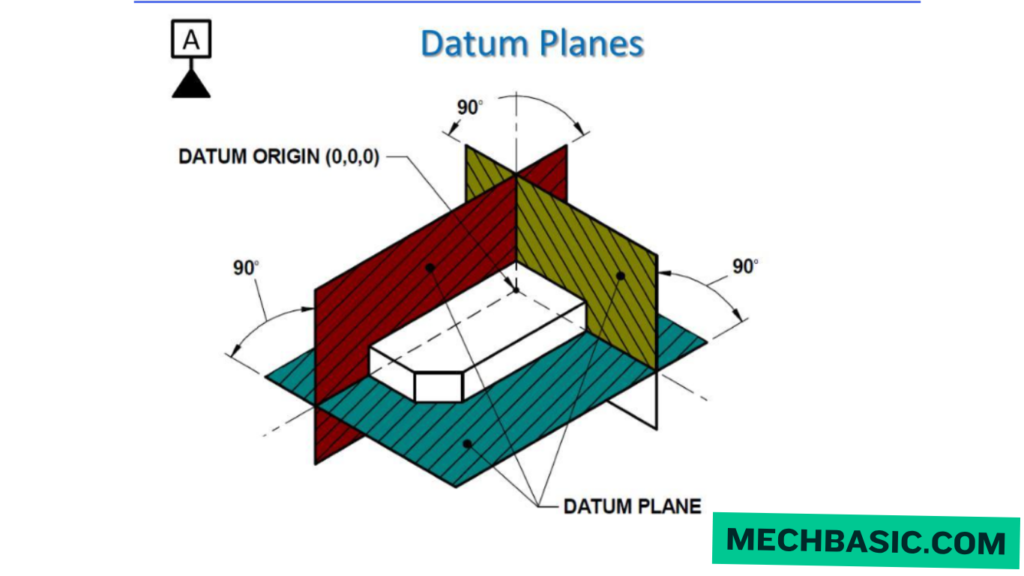
What are Datum Planes?
A datum plane is a theoretical reference plane used in engineering, mechanical design, manufacturing, inspection, and metrology. It provides a fixed and common reference from which the position, size, orientation, and geometry of other features can be defined or measured.
In simple words:
A datum plane is a reference surface that tells us “where to start measuring from.”
For example, if you want to specify the position of a hole on a machine component, saying “the hole is 20 mm from the edge” may not be sufficiently precise. Instead, you can establish a datum plane and specify that the hole’s center is 20 mm from the datum.
Why Are Datum Planes Important?
1. Provides a common reference
The most important purpose of a datum plane is to establish a common reference.
Suppose a component has several holes, slots, and surfaces. If every dimension is measured from a different edge, errors can accumulate.
A datum plane allows all important dimensions to be related to the same reference.
Example:
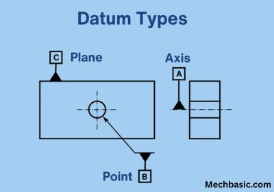
If the datum plane is taken as the bottom surface:
- Hole A → 20 mm above datum
- Hole B → 50 mm above datum
- Slot → 75 mm above datum
This gives everyone—designer, machinist, and inspector—the same reference.
2. Helps define the location of features
Datum planes are essential for specifying the exact location of features.
For example, consider a rectangular plate:
             Hole
              ○
              |
              | 40 mm
              |
   ───────────┼────────────
       Datum Plane
If the datum plane is the bottom surface, the hole can be specified as being 40 mm from the datum.
This removes ambiguity about where the measurement should be taken.
3. Controls orientation
Datum planes are not only used for location; they also control orientation.
A feature may need to be:
- Parallel to a datum
- Perpendicular to a datum
- At a specified angle to a datum
For example, if a shaft mounting surface must be perpendicular to the base, the base can be established as a datum plane.
The perpendicularity requirement can then be controlled relative to that datum.
4. Important in GD&T
Datum planes are fundamental to Geometric Dimensioning and Tolerancing (GD&T).
GD&T uses datums to control geometric characteristics such as:
- Straightness
- Flatness
- Parallelism
- Perpendicularity
- Angularity
- Position
- Profile
- Runout
A datum establishes the reference system against which these requirements are evaluated.
For example:
⌀0.05 | A | B | C
can indicate that a feature’s position is controlled relative to datum features A, B, and C.
Without datums, many GD&T specifications would not have a clear reference.
5. Reduces manufacturing errors
During manufacturing, the machinist needs to know which surface or feature should be used as the reference.
A datum plane provides this information.
For example, during milling:
- The machine establishes the datum surface.
- The workpiece is positioned relative to that surface.
- Other dimensions are machined from the established reference.
This makes manufacturing more consistent.
6. Prevents accumulation of dimensional errors
Consider a component with three dimensions:
Datum ──20── Feature 1 ──30── Feature 2 ──40── Feature 3If each feature is dimensioned from the previous feature, manufacturing errors can accumulate.
Instead:
Datum ──20── Feature 1
Datum ─────50──── Feature 2
Datum ─────────90──────── Feature 3
Now each feature has a direct relationship with the datum.
This is called baseline dimensioning, and it can significantly reduce the effect of accumulated tolerances.
7. Essential for inspection and measurement
After a component is manufactured, an inspector has to determine whether it meets the drawing requirements.
The inspector needs a known reference.
Datum planes provide that reference.
For example, using a Coordinate Measuring Machine (CMM), the inspector can:
- Establish Datum A.
- Establish Datum B.
- Establish Datum C.
- Create a coordinate system.
- Measure the component’s features relative to that system.
This allows the actual component to be compared with the design requirements.
8. Establishes a coordinate system
Multiple datum planes can be used together to establish a datum reference frame.
Typically, three mutually related references can establish the component’s:
- X direction
- Y direction
- Z direction
- Origin/location
- Orientation
A common concept is the 3-2-1 locating principle:
| Reference | Typical purpose |
|---|---|
| Primary datum | Controls 3 degrees of freedom |
| Secondary datum | Controls 2 degrees of freedom |
| Tertiary datum | Controls 1 degree of freedom |
Together, they can fully locate a rigid component.
9. Important for assembly
Datum planes are extremely important when different components must fit together.
Imagine an engine component that must be mounted onto a base.
The designer might specify:
- Bottom surface → Datum A
- Side surface → Datum B
- End surface → Datum C
The mating components can then be manufactured and inspected using the same references.
This improves interchangeability.
A correctly manufactured part should fit another correctly manufactured part without requiring individual adjustment.
10. Improves interchangeability
In mass production, thousands or millions of identical parts may be produced.
Each part cannot be individually adjusted to fit.
Datum systems ensure that important features are located consistently.
For example:
Automotive manufacturing
A mounting bracket may have several bolt holes. Their locations must be consistent so that the bracket fits every vehicle of the same model.
Datums provide the common reference needed to maintain this consistency.
11. Useful in CNC machining
Datum planes are particularly important in CNC machining.
The CNC machine requires a coordinate system or work offset.
A datum can be used to establish:
- Workpiece zero
- X-zero
- Y-zero
- Z-zero
- Tool movement references
For example:
             Z
             ↑
             |
             |
     ┌──────────────┐
     │   WORKPIECE  │
     │              │
     └──────────────┘
────────────┴──────────── → X
          Datum
Once the datum is established, CNC coordinates can be programmed relative to it.
12. Makes engineering drawings easier to understand
Without datum references, an engineering drawing can become confusing.
Compare:
Without datum:
Hole location = 35 mm from some edge.
Which edge? What if the edge isn’t manufactured accurately?
With datum:
Hole position is controlled relative to Datum A and Datum B.
Now the designer, manufacturer, and inspector have a common understanding.
13. Helps control functional surfaces
The most important surfaces of a component should generally be used as references when appropriate.
For example, in a bearing housing:
- The mounting surface may be the primary datum.
- A side surface may be the secondary datum.
- An end surface may be the tertiary datum.
This ensures that the bearing location is controlled relative to the surfaces that actually matter during operation.
In summary
Datum planes are important because they provide a stable, common, and unambiguous reference for designing, manufacturing, assembling, and inspecting components.
Main advantages
- Provides a common reference
- Defines feature locations
- Controls orientation
- Forms the basis of GD&T
- Reduces manufacturing errors
- Prevents accumulation of tolerances
- Makes inspection easier
- Establishes coordinate systems
- Improves assembly accuracy
- Provides interchangeability
- Helps CNC machining
- Makes engineering drawings clearer
- Controls functionally important surfaces
- Improves overall product quality
Datum planes are important because they provide a fixed and common reference for locating, orienting, dimensioning, manufacturing, assembling, and inspecting engineering components accurately and consistently.
Latest articles:

Best Budget Workstation Laptops for SolidWorks and Heavy 3D Assembly Modeling
Best Budget Workstation Laptops for SolidWorks and Heavy 3D Assembly Modeling Overview What Does SOLIDWORKS…

SolidWorks Standard vs Professional vs Premium: Full Feature Comparison
SolidWorks Standard vs Professional vs Premium: Full Feature Comparison Overview: SOLIDWORKS Package Overview SOLIDWORKS comes…

SolidWorks 2026 License Cost: Perpetual vs Subscription Pricing Breakdown
SolidWorks 2026 License Cost: Perpetual vs Subscription Pricing Breakdown Overview: SOLIDWORKS 2026 License Options SOLIDWORKS…

Flatness-GD&T | GD&T Tutorials

ANSI vs ISO Standards-Key Differences you need to know

Straightness-GD&T | GD&T Tutorials
Related Tags:
Also read: Datum Feature
Categories:




















