
Key Takeaways:
What is Drafting in Design?
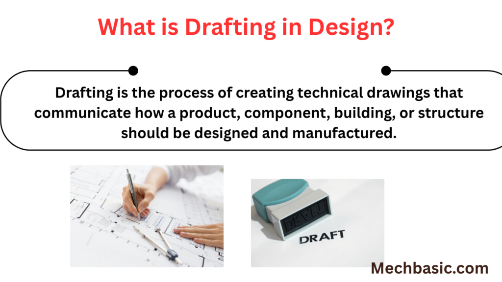
Drafting is the process of creating technical drawings that communicate how a product, component, building, or structure should be designed and manufactured.
Key Elements of Drafting
- Geometry – Lines, circles, arcs, and shapes
- Dimensions – Exact sizes and measurements
- Annotations – Notes, symbols, and specifications
- Views – Front, top, side, section, and isometric views
- Tolerances – Permitted variation in dimensions
- Materials & Manufacturing Details – Information needed to produce the design
Types of Drafting
2D Drafting → Technical drawings and layouts
3D Drafting → 3D models and detailed views
Mechanical Drafting → Machine parts and assemblies
Architectural Drafting → Building plans and construction drawings
Civil Drafting → Roads, sites, structures, and infrastructure
CAD Drafting
Modern drafting is usually performed using CAD software such as AutoCAD, SOLIDWORKS, CATIA, and Autodesk Inventor, which improves accuracy and makes design changes easier.
Workflow
Design Idea → Drafting → Detailed Technical Drawing → Manufacturing / Construction
In this article:
What is Drafting in Design?
Drafting in design is the process of creating accurate technical drawings and visual representations of an object, component, structure, or system. Drafting communicates important design information such as dimensions, shapes, materials, tolerances, specifications, and manufacturing requirements.
Traditionally, drafting was performed by hand using drawing boards and technical instruments. Today, most professional drafting is completed using CAD (Computer-Aided Design) software such as AutoCAD, SOLIDWORKS, CATIA, Creo, and other engineering design tools.
Drafting is an important part of the engineering and design process because it converts design concepts into clear technical documentation that can be understood by engineers, manufacturers, architects, contractors, and other professionals.
Key Elements of Drafting
A good technical drawing contains several important elements that communicate the design accurately.
1. Lines
Different line types are used to represent different features.
Common examples include:
- Object lines
- Hidden lines
- Center lines
- Construction lines
- Section lines
- Dimension lines
- Extension lines
Each line type has a specific meaning in technical drawing.
2. Dimensions
Dimensions communicate the size and location of features.
They can specify:
- Length
- Width
- Height
- Diameter
- Radius
- Angles
- Hole locations
- Distances between features
Accurate dimensioning is essential for manufacturing and construction.
3. Symbols
Technical drawings use standardized symbols to communicate information efficiently.
Examples include:
- Diameter symbol
- Radius symbol
- Surface-finish symbols
- Welding symbols
- Geometric-tolerance symbols
- Datum symbols
4. Scale
Scale determines the relationship between the drawing size and the actual object size.
Examples include:
- 1:1 — Full size
- 1:2 — Half size
- 2:1 — Double size
- 1:10 — Reduced size
The appropriate scale allows large or small objects to be represented clearly on a drawing sheet.
5. Views
Multiple views may be required to communicate a 3D object accurately.
Common drawing views include:
- Front view
- Top view
- Right-side view
- Left-side view
- Bottom view
- Isometric view
- Section view
- Detail view
6. Tolerances
Manufactured components cannot always be produced to an infinitely exact dimension.
Tolerances define the acceptable variation from the specified dimension.
For example:
50 ± 0.05 mm
means the acceptable dimension can range from:
49.95 mm to 50.05 mm
7. Title Block
A drawing’s title block provides important document information.
It may contain:
- Drawing title
- Drawing number
- Designer
- Company name
- Date
- Scale
- Material
- Revision
- Drawing standard
- Sheet number
Types of Drafting
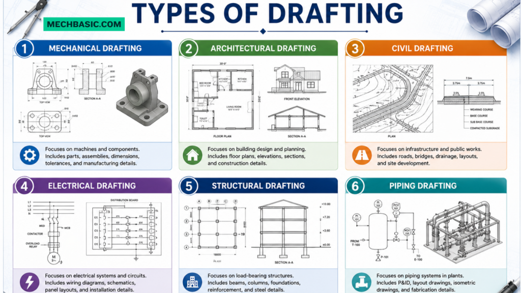
Drafting can be classified according to the industry and purpose of the drawing.
1. Mechanical Drafting
Mechanical drafting is used to communicate the design and manufacturing requirements of mechanical components and machines.
Applications include:
- Machine parts
- Gearboxes
- Pumps
- Brackets
- Shafts
- Fixtures
- Industrial equipment
2. Architectural Drafting
Architectural drafting represents buildings and other structures.
It can include:
- Floor plans
- Elevations
- Sections
- Roof plans
- Building details
- Construction drawings
3. Civil Drafting
Civil drafting is used for infrastructure and civil-engineering projects.
Examples include:
- Roads
- Bridges
- Drainage systems
- Site plans
- Utilities
- Land-development drawings
4. Electrical Drafting
Electrical drafting communicates electrical systems and installations.
Examples include:
- Wiring diagrams
- Circuit diagrams
- Panel layouts
- Electrical schematics
- Control-system drawings
5. Structural Drafting
Structural drafting focuses on the structural components of buildings and other structures.
Applications include:
- Steel structures
- Reinforced concrete
- Beams
- Columns
- Foundations
- Structural connections
6. Piping Drafting
Piping drafting is used in industrial and process facilities.
Drawings can show:
- Pipes
- Valves
- Pumps
- Fittings
- Pipe supports
- Equipment connections
CAD Drafting
CAD drafting is the use of computer software to create, modify, organize, and document technical drawings.
Instead of drawing lines and dimensions manually, CAD software allows designers to create accurate digital drawings.
Common CAD Software
- AutoCAD
- SOLIDWORKS
- CATIA
- Creo
- Siemens NX
- Fusion
- DraftSight
- Onshape
Advantages of CAD Drafting
1. Higher Accuracy
CAD allows designers to create highly precise geometry and dimensions.
2. Faster Design Changes
Dimensions and geometry can be modified without recreating the entire drawing.
3. Easy Editing
Designers can quickly:
- Move objects
- Copy features
- Modify dimensions
- Delete geometry
- Add annotations
4. Reusable Components
Blocks, symbols, templates, libraries, and standard components can be reused across projects.
5. Better Documentation
CAD makes it easier to produce:
- Manufacturing drawings
- Assembly drawings
- Construction drawings
- Detailed documentation
6. Easy Digital Sharing
CAD files can be shared electronically between:
- Engineers
- Designers
- Manufacturers
- Contractors
- Clients
Drafting vs. Design
Drafting and design are related but not exactly the same.
| Design | Drafting |
|---|---|
| Develops the engineering concept | Documents the design |
| Solves engineering problems | Communicates technical information |
| Determines how a product should work | Shows how the product should be made |
| May involve calculations and analysis | Focuses heavily on drawings and documentation |
| Includes concept development | Includes dimensions, views, symbols, and notes |
In many modern engineering workflows, design and drafting work together.
Drafting Standards
Technical drafting often follows established standards to ensure drawings are consistent and understandable.
Common standards include:
- ISO
- ASME
- DIN
- BS
- JIS
Standards can define conventions for:
- Line types
- Dimensioning
- Symbols
- Tolerances
- Drawing layouts
- Projection methods
Using the appropriate drafting standard is particularly important when drawings are shared between organizations or used for manufacturing.
Frequently Asked Questions (FAQs)
1. What is drafting in design?
Drafting is the process of creating technical drawings that communicate the shape, dimensions, specifications, and manufacturing or construction requirements of a design.
2. What is the purpose of drafting?
The main purpose of drafting is to communicate design information accurately so that a component, product, building, or system can be manufactured or constructed correctly.
3. Is drafting the same as design?
No. Design focuses on developing and solving the engineering problem, while drafting focuses on accurately documenting and communicating the resulting design.
4. What is CAD drafting?
CAD drafting is the creation of technical drawings using computer-aided design software instead of traditional manual drafting methods.
5. What software is used for drafting?
Popular drafting software includes AutoCAD, SOLIDWORKS, CATIA, Creo, Siemens NX, Fusion, DraftSight, and Onshape.
6. What skills are needed for drafting?
Important skills include:
- Technical drawing
- Dimensioning
- Geometric tolerancing
- CAD software
- Engineering standards
- Visualization
- Attention to detail
7. What are the main types of drafting?
Common types include:
- Mechanical drafting
- Architectural drafting
- Civil drafting
- Electrical drafting
- Structural drafting
- Piping drafting
8. Is drafting still a good career?
Yes. Drafting remains important in engineering, manufacturing, construction, architecture, and product development. Modern drafting careers increasingly combine traditional technical-drawing knowledge with CAD, 3D modeling, BIM, and digital engineering skills.
9. Can engineers use drafting skills?
Yes. Engineers frequently use drafting principles to create and interpret engineering drawings, even when specialized CAD designers or drafters prepare the final documentation.
10. What is the difference between 2D drafting and 3D CAD?
2D drafting represents designs using drawings, lines, dimensions, and annotations. 3D CAD creates a three-dimensional digital model that can provide additional information about geometry, assemblies, materials, and design intent.
Conclusion
Drafting in design is the process of transforming design information into accurate and understandable technical documentation. It provides the communication link between design concepts and real-world manufacturing or construction.
Modern CAD drafting has made this process faster, more accurate, and easier to modify and share. Whether used in mechanical engineering, architecture, civil engineering, electrical design, structural engineering, or manufacturing, drafting remains an essential technical skill.
For students and professionals, learning technical drawing principles + CAD software + dimensioning and tolerancing + relevant drafting standards provides a strong foundation for careers in modern engineering and design.
Also read: What is CAD?-Comprehensive Guide.
Latest articles:

10 skills to get Draftsmen job ready
8 Types of Drafting you need to know
What is Drafting in Design?-Everything you need to know
What is Drafting in Design?-Everything you need to know Key Takeaways: What is Drafting in…
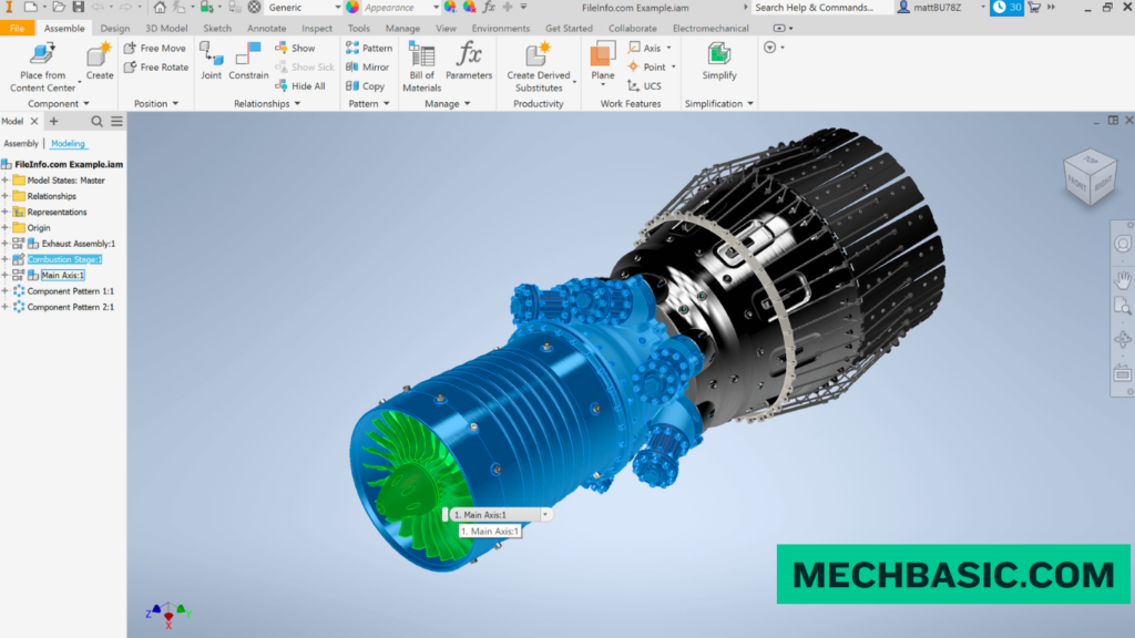
AutoCAD vs Autodesk Inventor-Everything you need to know
Key Takeaways: AutoCAD vs. Autodesk Inventor What is Autodesk Inventor? Autodesk Inventor is a 3D…
Best way to import excel data in AutoCAD
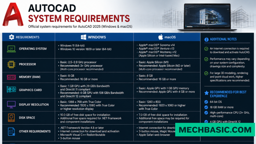
AutoCAD system requirements-Everything you need to know
Related Tags:
Categories:




















