
Key Takeaways:
How to Change Units in AutoCAD
1. Use the UNITS Command
Type UNITS in the command line and press Enter.
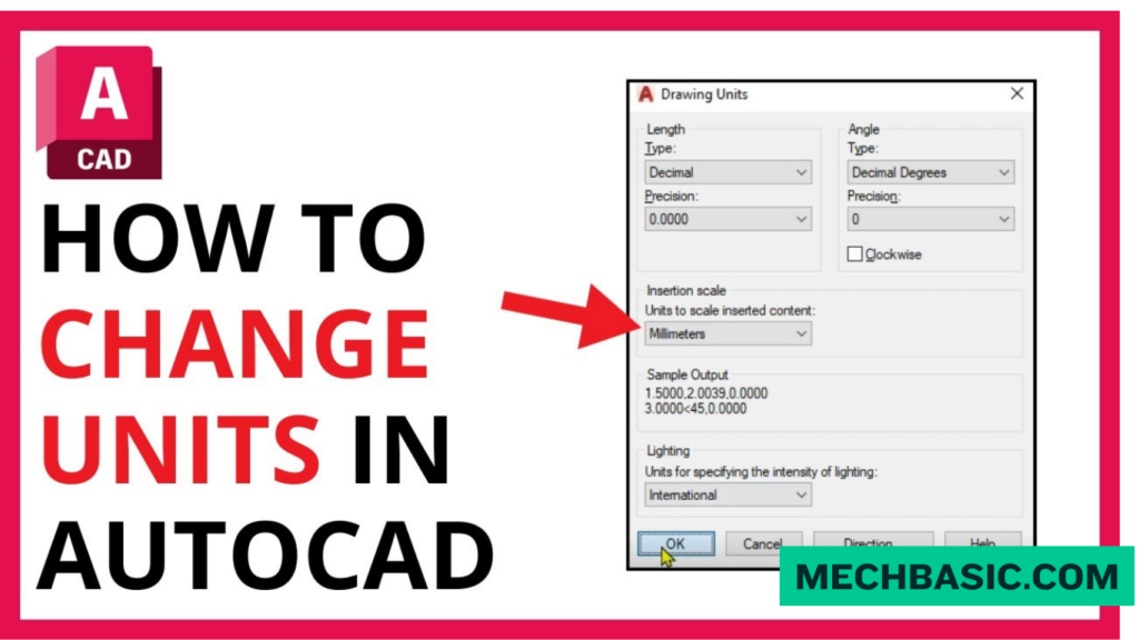
In the Drawing Units dialog box:
- Length Type: Select Decimal, Architectural, Engineering, etc.
- Insertion Scale: Select the required unit, such as Millimeters, Centimeters, Meters, or Inches.
- Precision: Choose the number of decimal places.
- Click OK.
2. Common AutoCAD Units
| Unit | Typical Use |
|---|---|
| Millimeters (mm) | Mechanical & engineering drawings |
| Meters (m) | Civil/site plans |
| Inches (in) | US engineering drawings |
| Feet (ft) | Architecture & construction |
| Decimal | General technical drawings |
3. Important: UNITS Does Not Scale Existing Geometry
Changing the drawing units does not automatically convert the size of objects already drawn.
For example, if a line is currently 100 units long and you need to convert it from inches to millimeters:
100 × 25.4 = 2540 mm
4. Convert an Existing Drawing
Use the SCALE command to physically resize existing geometry.
For example, inches → millimeters:
Select Objects → SCALE → Base Point → Enter 25.4
For millimeters → inches:
Scale factor = 0.03937
Key Takeaway
UNITS → Set Length & Insertion Scale → OK
Need to actually convert the drawing? → SCALE → Use the appropriate conversion factor.
In this article:
How to Change Units in AutoCAD
Setting the correct drawing units in AutoCAD is important for accurate design, drafting, dimensioning, and documentation. AutoCAD allows you to specify how distances and angles are interpreted and displayed.
The UNITS command is commonly used to configure the drawing’s unit settings. However, an important point to remember is that changing the UNITS settings does not automatically resize existing geometry.
1. Use the UNITS Command
The easiest way to configure AutoCAD drawing units is with the UNITS command.
Step 1: Open the Units Dialog Box
UNITS
in the command line and press Enter.
The Drawing Units dialog box will open.
Step 2: Set the Length Type
Under Length, select the appropriate type.
Common options include:
- Decimal
- Architectural
- Engineering
- Fractional
- Scientific
For most engineering drawings, Decimal is commonly used.
Step 3: Set the Precision
Choose the number of decimal places you want AutoCAD to display.
For example:
- 0
- 0.0
- 0.00
- 0.000
The precision controls how values are displayed, not the physical size of the geometry.
Step 4: Set the Angle Type
Under Angle, select the required format.
Common options include:
- Decimal Degrees
- Degrees/Minutes/Seconds
- Grads
- Radians
- Surveyor’s Units
For many engineering workflows:
Decimal Degrees
is a convenient choice.
Step 5: Set Insertion Scale
The Insertion Scale setting controls how objects created in one drawing are interpreted when inserted into another drawing with different unit settings.
Common choices include:
- Millimeters
- Centimeters
- Meters
- Inches
- Feet
- Unitless
For example, if you are working on a mechanical drawing in millimeters, select:
Millimeters
Step 6: Click OK
After configuring the settings, click:
OK
Your drawing’s unit-display and insertion settings are now configured.
2. Common AutoCAD Units
Different industries commonly use different units.
Millimeters (mm)
Widely used for:
- Mechanical drawings
- Manufacturing
- Engineering
- Architectural details
- MEP drawings
Example:
500 mm
Meters (m)
Commonly used for:
- Civil engineering
- Site plans
- Large buildings
- Infrastructure projects
- Land development
Example:
25 m
Centimeters (cm)
Used in some architectural, design, and technical workflows.
Example:
50 cm
Inches (in)
Common in:
- US engineering
- Manufacturing
- Architectural drawings
- Mechanical design
Example:
12 in
Feet (ft)
Common in:
- US construction
- Architecture
- Civil engineering
- Building plans
Example:
20 ft
3. Important: UNITS Does Not Scale Existing Geometry
This is one of the most important things to understand about AutoCAD units.
Changing the setting in:
UNITS
does not automatically make existing geometry larger or smaller.
For example, suppose you have a line whose AutoCAD length is:
100
If you change the drawing’s unit setting from millimeters to meters, the line does not automatically become 1000 mm or 0.1 m.
The geometry itself remains the same size in drawing coordinates.
UNITS controls:
- How units are interpreted
- How values are displayed
- Insertion-unit behavior
UNITS does not:
- Automatically resize existing geometry
- Convert all existing dimensions
- Change the coordinates of your objects
Common Unit Conversion Scale Factors
| Conversion | Scale Factor |
|---|---|
| mm → m | 0.001 |
| m → mm | 1000 |
| cm → m | 0.01 |
| m → cm | 100 |
| in → ft | 0.0833333 |
| ft → in | 12 |
These factors are used when you need to physically convert existing geometry, rather than merely change the unit settings.
Autodesk Support: How to Convert Drawing Units Within a File: Direct instructions for converting between units (e.g., millimeters to meters) and matching INSUNITS to active drawing units.
Best Practices
1. Decide Units Before Starting
For a new project, establish whether you will work in:
mm, cm, m, inches, or feet
before creating significant geometry.
2. Check Units When Receiving Drawings
Always verify the units of external DWG files before combining them with your drawing.
3. Verify a Known Dimension
Use DIST or the Properties palette to check a known dimension before scaling an existing drawing.
4. Use Templates
Create project templates with the correct units, layers, styles, and other CAD standards already configured.
5. Be Careful With Xrefs and Blocks
Different drawings can use different unit settings. Incorrect insertion-unit configuration can cause blocks or external references to appear at the wrong size.
Frequently Asked Questions (FAQs)
1. What command changes units in AutoCAD?
Use the:
UNITS
command.
2. Does changing UNITS resize my drawing?
No. The UNITS command changes unit settings and interpretation; it does not automatically scale existing geometry.
3. How do I convert an existing drawing from meters to millimeters?
Use SCALE with a factor of 1000, then configure the appropriate unit settings.
4. How do I convert millimeters to meters?
Use SCALE with a factor of 0.001.
5. Which unit is commonly used in mechanical AutoCAD drawings?
Millimeters are commonly used in many mechanical and manufacturing workflows.
6. Which units are commonly used in civil drawings?
Depending on the project and regional standards, meters, millimeters, feet, or inches may be used.
Conclusion
Changing units in AutoCAD is a two-part concept:
Configure Units
UNITS → Set Length/Angle → Set Insertion Scale → OK
Convert Existing Geometry
SCALE → Select Objects → Base Point → Enter Conversion Factor
The key point is:
UNITS changes how AutoCAD interprets and displays units; SCALE changes the actual size of existing geometry.
Always verify a known dimension after converting a drawing to ensure that the geometry is at the intended scale.
Latest articles:

Best Budget Workstation Laptops for SolidWorks and Heavy 3D Assembly Modeling
Best Budget Workstation Laptops for SolidWorks and Heavy 3D Assembly Modeling Overview What Does SOLIDWORKS…

SolidWorks Standard vs Professional vs Premium: Full Feature Comparison
SolidWorks Standard vs Professional vs Premium: Full Feature Comparison Overview: SOLIDWORKS Package Overview SOLIDWORKS comes…

SolidWorks 2026 License Cost: Perpetual vs Subscription Pricing Breakdown
SolidWorks 2026 License Cost: Perpetual vs Subscription Pricing Breakdown Overview: SOLIDWORKS 2026 License Options SOLIDWORKS…

Flatness-GD&T | GD&T Tutorials

ANSI vs ISO Standards-Key Differences you need to know

Straightness-GD&T | GD&T Tutorials
Categories:




















