
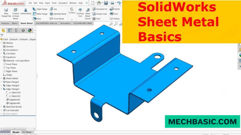
key Takeaways:
SOLIDWORKS Sheet Metal
What is SOLIDWORKS Sheet Metal?
SOLIDWORKS Sheet Metal is a specialized design environment used to create thin, flat metal components that can be bent, folded, cut, and manufactured. It helps engineers design sheet-metal parts and automatically generate accurate flat patterns for fabrication.
Key Features
- Base Flange/Tab – Creates the basic sheet-metal body.
- Edge Flange – Adds bends along selected edges.
- Sketched Bend – Creates bends using a sketch.
- Sheet Metal Gusset – Adds reinforcement to sheet-metal parts.
- Hem – Creates folded edges for strength and safety.
- Jog – Creates offset bends.
- Forming Tools – Creates louvers, embosses, and other formed features.
- Flatten – Unfolds the part to create a manufacturing-ready flat pattern.
Typical Workflow
Sketch → Base Flange → Add Bends → Add Cuts/Features → Apply Bend Allowance → Flatten → Create Drawing → Manufacture
Important Sheet-Metal Parameters
Sheet-metal design depends on thickness, bend radius, bend allowance, K-factor, bend deduction, and material properties to produce an accurate flat pattern.
Applications
SOLIDWORKS Sheet Metal is commonly used for automotive components, electrical enclosures, machine guards, brackets, cabinets, HVAC components, panels, and industrial equipment.
Key Takeaway
3D Sheet-Metal Model → Bends & Features → Flatten → Flat Pattern → CNC/Laser Cutting → Bending → Finished Part
In this article:
SOLIDWORKS Sheet Metal
SOLIDWORKS Sheet Metal is a specialized set of tools used to design, modify, and manufacture components made from thin metal sheets. It allows engineers and designers to create accurate 3D sheet-metal models while maintaining the manufacturing information needed to produce flat patterns and fabricated parts.
SOLIDWORKS Sheet Metal is widely used for products such as enclosures, brackets, cabinets, panels, ducts, machine covers, electrical boxes, and automotive components.
One of its major advantages is that a 3D folded model can be converted into a flat pattern for cutting and manufacturing.
What is SOLIDWORKS Sheet Metal?
SOLIDWORKS Sheet Metal is a collection of parametric modeling tools specifically designed for sheet-metal parts.
Unlike ordinary solid modeling, sheet-metal design takes manufacturing processes into account, including:
- Bending
- Cutting
- Folding
- Unfolding
- Bending allowances
- Bend relief
- Corner treatment
- Flat-pattern generation
A typical workflow is:
Flat Sheet → Bend → Fold → 3D Part → Flatten → Manufacturing
This makes it possible to design the finished component while also generating the geometry required for fabrication.
SOLIDWORKS Help: Sheet Metal Design Overview: Official Dassault Systèmes documentation covering base flanges, bend allowance parameters (K-factor, Bend Deduction), flat pattern generation, and forming tools.
Key Features
1. Base Flange/Tab
The Base Flange/Tab feature is commonly used as the starting point for a sheet-metal component.
You create a sketch and specify:
- Sheet thickness
- Bend radius
- Bend direction
- Material type
SOLIDWORKS then creates the initial sheet-metal body.
2. Edge Flange
Edge Flange creates a flange from an existing edge.
It is useful for creating:
- Side walls
- Mounting flanges
- Enclosure panels
- Structural bends
You can control parameters such as:
- Flange length
- Angle
- Bend position
- Bend radius
3. Sketched Bend
The Sketched Bend feature allows you to create a bend along a defined sketch line.
It is useful when the bend location is not simply an existing model edge.
4. Hem
A Hem folds the sheet edge back onto itself.
Hems are commonly used to:
- Remove sharp edges
- Increase edge stiffness
- Improve appearance
- Provide safer finished edges
5. Jog
A Jog creates two bends that offset a section of sheet metal.
It can be useful for:
- Mounting offsets
- Clearance
- Structural changes
- Joining components
6. Sheet Metal Gusset
A sheet-metal gusset can reinforce a bent component and improve structural rigidity.
7. Corner Treatment
SOLIDWORKS provides tools for managing sheet-metal corners.
These can help with:
- Corner gaps
- Overlapping bends
- Manufacturing clearance
- Cleaner finished geometry
8. Flattening
The Flatten function unfolds the sheet-metal model into its flat condition.
This is extremely important for manufacturing.
The flattened model can be used to create:
- DXF files
- Laser-cutting profiles
- Plasma-cutting profiles
- Manufacturing drawings
Typical Workflow
A common SOLIDWORKS Sheet Metal workflow is:
Step 1: Create a New Part
Start a new SOLIDWORKS part.
Step 2: Create the Base Flange
Create a sketch representing the initial sheet profile.
Then use:
Sheet Metal → Base Flange/Tab
Specify the required:
- Thickness
- Bend radius
- Bend allowance
Step 3: Add Flanges
Use Edge Flange to create additional walls or bends.
For example:
Base → Side Wall → Rear Wall → Front Wall
Step 4: Add Cuts and Holes
Use normal sketch-based cutting tools or sheet-metal features to create:
- Holes
- Slots
- Mounting openings
- Ventilation openings
- Cable passages
Step 5: Add Manufacturing Details
Add features such as:
- Hems
- Jogs
- Bend relief
- Corner treatments
- Gussets
Step 6: Flatten the Part
Use:
Flatten
to create the developed sheet-metal shape.
This allows you to verify that the part can be unfolded correctly.
Step 7: Create the Manufacturing Drawing
Create a drawing showing:
- Folded views
- Flat-pattern view
- Dimensions
- Bend information
- Material
- Thickness
- Notes
Step 8: Export the Flat Pattern
The flat pattern can be exported to formats such as:
DXF/DWG
for use with manufacturing equipment and downstream fabrication workflows.
Important Sheet-Metal Parameters
Correct sheet-metal parameters are essential because they determine how the flat pattern relates to the finished bent component.
1. Sheet Thickness
Thickness is the distance between the two surfaces of the sheet.
Examples:
- 1 mm
- 1.5 mm
- 2 mm
- 3 mm
The correct value should match the actual material being manufactured.
2. Bend Radius
The inside bend radius defines the radius of the sheet’s inside surface at the bend.
For example:
Thickness = 2 mm
Inside Bend Radius = 2 mm
The appropriate radius depends on the material, tooling, thickness, and manufacturing process.
3. Bend Angle
The bend angle determines how much the sheet is folded.
For example:
90° bend
is one of the most common sheet-metal bends.
4. Bend Allowance
Bend allowance accounts for the material consumed by the bend region.
It helps determine the correct flat length before bending.
5. K-Factor
The K-factor describes the location of the neutral axis within the sheet thickness during bending.
A simplified relationship is:
K = Neutral Axis Distance / Sheet Thickness
The K-factor is used in calculating the developed flat pattern.
The appropriate value depends on factors such as:
- Material
- Thickness
- Bend radius
- Bending process
- Tooling
6. Bend Deduction
Bend deduction is another method used to calculate the flat length of a bent sheet-metal component.
It relates the overall dimensions of the finished bent part to the required developed length.
7. Bend Relief
Bend relief prevents unwanted tearing or deformation around the end of a bend.
It is particularly important when two bends meet near an edge.
Applications
SOLIDWORKS Sheet Metal is used across many industries.
Mechanical Engineering
- Machine covers
- Brackets
- Frames
- Guards
- Mounting plates
Electrical Engineering
- Electrical enclosures
- Control panels
- Junction boxes
- Equipment cabinets
HVAC
- Air ducts
- Ventilation components
- Equipment housings
Automotive
- Vehicle brackets
- Shields
- Mounting components
- Body components
Industrial Equipment
- Machine enclosures
- Control cabinets
- Protective guards
- Equipment panels
Consumer Products
- Product housings
- Metal cabinets
- Appliance components
Sheet Metal vs. Regular Solid Modeling
| Feature | Sheet Metal | Regular Solid Modeling |
|---|---|---|
| Designed for thin metal | Yes | Possible |
| Bend operations | Specialized | Manual |
| Flat pattern | Automatic | Not inherently |
| Bend allowance | Integrated | Manual |
| DXF flat pattern | Easy | More involved |
| Manufacturing workflow | Excellent | General |
| Complex solid geometry | Limited compared with general solid tools | Excellent |
For a component that will actually be cut and bent from sheet material, dedicated sheet-metal features are generally preferable.
Example: Sheet-Metal Enclosure
Suppose you need to design a simple electrical enclosure.
Workflow
Create Base Flange
↓
Set Thickness
↓
Create Edge Flanges
↓
Add Mounting Holes
↓
Add Corner Treatments
↓
Add Bend Relief
↓
Flatten
↓
Create Drawing
↓
Export DXF
This produces both the finished 3D enclosure and the flat geometry required for fabrication.
Best Practices
1. Use the Actual Material Thickness
Do not arbitrarily choose thickness. Match the CAD model to the material that will actually be manufactured.
2. Use Realistic Bend Radii
The bend radius should be compatible with the material and available forming equipment.
3. Configure Bend Allowance Correctly
Incorrect bend parameters can result in flat patterns that do not produce the intended finished dimensions.
4. Check the Flat Pattern
Always inspect the flattened part before sending it for manufacturing.
5. Consider Manufacturing Constraints
Design around the capabilities of the actual:
- Laser cutter
- Press brake
- Punching machine
- Shearing equipment
- Welding process
Frequently Asked Questions (FAQs)
1. What is SOLIDWORKS Sheet Metal used for?
It is used to design components manufactured from sheet material through processes such as cutting, bending, folding, and forming.
2. Can SOLIDWORKS create a flat pattern?
Yes. Sheet-metal parts can be flattened to generate the developed geometry required for manufacturing.
3. What is K-factor in SOLIDWORKS Sheet Metal?
K-factor represents the position of the neutral axis through the sheet thickness during bending and is used in flat-pattern calculations.
4. Can I export a sheet-metal flat pattern to DXF?
Yes. A sheet-metal flat pattern can be exported to DXF/DWG for many downstream fabrication workflows.
5. What is the difference between Base Flange and Edge Flange?
Base Flange/Tab generally creates the initial sheet-metal body, while Edge Flange adds a bent flange from an existing edge.
Conclusion
SOLIDWORKS Sheet Metal provides a complete workflow for designing and manufacturing thin-sheet components.
The typical process is:
Create Base Flange → Add Flanges → Add Cuts/Holes → Apply Bend Details → Flatten → Create Drawing → Export DXF
The most important parameters to understand are sheet thickness, bend radius, bend angle, bend allowance, K-factor, and bend relief.
By combining accurate sheet-metal parameters with proper manufacturing considerations, SOLIDWORKS can help engineers create designs that are not only visually correct in 3D but also practical to fabricate in the real world.
Latest articles:

SolidWorks Standard vs Professional vs Premium: Full Feature Comparison
SolidWorks Standard vs Professional vs Premium: Full Feature Comparison Overview: SOLIDWORKS Package Overview SOLIDWORKS comes…

SolidWorks 2026 License Cost: Perpetual vs Subscription Pricing Breakdown
SolidWorks 2026 License Cost: Perpetual vs Subscription Pricing Breakdown Overview: SOLIDWORKS 2026 License Options SOLIDWORKS…

Flatness-GD&T | GD&T Tutorials

ANSI vs ISO Standards-Key Differences you need to know

Straightness-GD&T | GD&T Tutorials
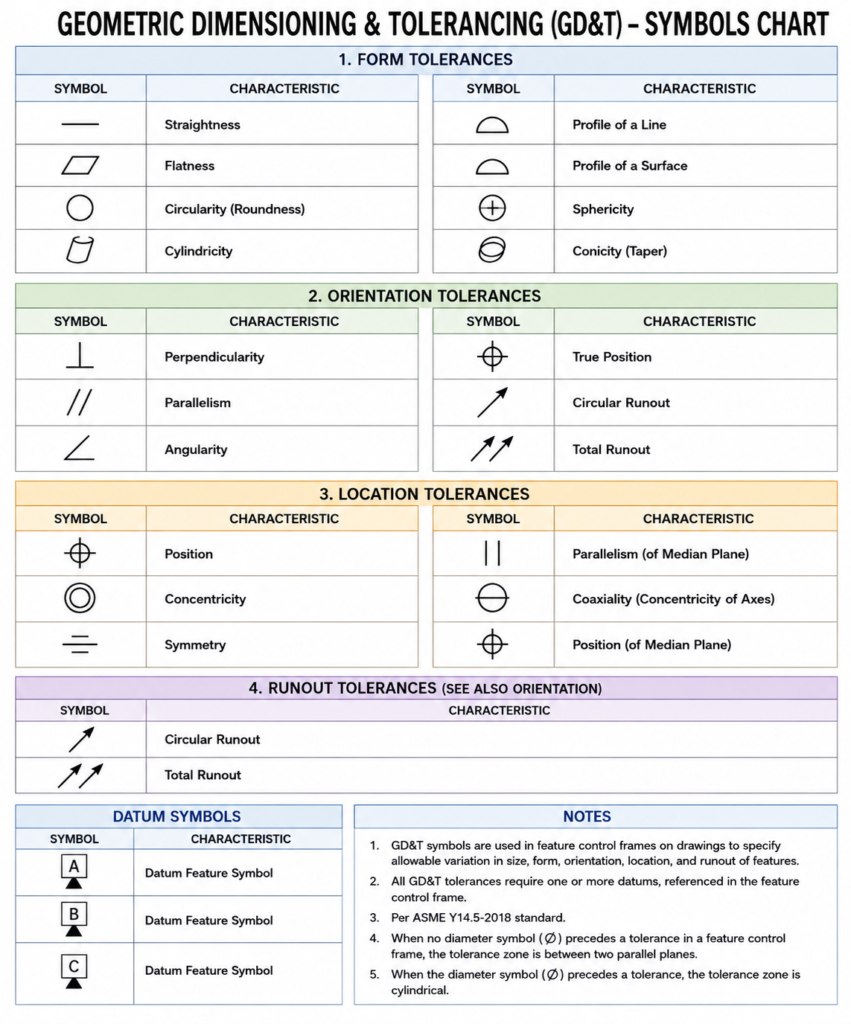
GD&T Symbols chart- Free download | GD&T
Geometric Dimensioning and Tolerancing (GD&T) is a standardized system used in engineering drawings to define…
Related tags:
Categories:




















