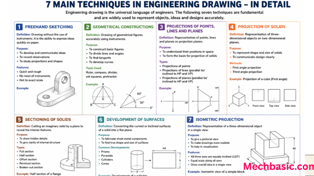
The 7 main techniques in engineering drawing are orthographic projection, isometric drawing, sectional views, dimensioning, scaling, geometric construction, and perspective drawing.
These techniques help represent objects accurately and clearly.
They are widely used in engineering, manufacturing, and design documentation.
In this article:
7 Main Techniques in Engineering Drawing
Engineering drawing uses standardized techniques to represent three-dimensional objects accurately on two-dimensional paper or screens. These techniques help engineers, designers, manufacturers, and technicians communicate technical information clearly.
1. Orthographic Projection
Definition
Orthographic projection is the most important technique in engineering drawing. It represents a 3D object using multiple 2D views.
Common Views
- Front View
- Top View
- Side View
Purpose
To show the exact shape and dimensions of an object without distortion.
Applications
- Machine parts
- Manufacturing drawings
- Assembly drawings
Example
A mechanical bracket may be shown using:
- Front view
- Top view
- Right-side view
This provides complete information for manufacturing.
Advantages
✔ Accurate dimensions
✔ Standardized method
✔ Easy to manufacture from
2. Isometric Drawing
Definition
An isometric drawing represents a 3D object in a single view.
Characteristics
- Three axes are 120° apart.
- Vertical lines remain vertical.
- Length, width, and height are visible simultaneously.
Purpose
To visualize the appearance of an object.
Applications
- Mechanical components
- Piping layouts
- Product designs
Advantages
✔ Easy visualization
✔ Shows three dimensions at once
3. Perspective Drawing
Definition
Perspective Drawing is a technique that represents objects as they appear to the human eye.
Characteristics
- Distant objects appear smaller.
- Parallel lines converge toward vanishing points.
Types
One-Point Perspective
Uses one vanishing point.
Two-Point Perspective
Uses two vanishing points.
Three-Point Perspective
Uses three vanishing points.
Applications
- Architecture
- Interior design
- Product presentation
Advantages
✔ Realistic appearance
4. Sectional Drawing
Definition
Sectional Drawing is a drawing created by imagining an object cut by a cutting plane.
Purpose
To reveal internal details that cannot be seen from outside.
Applications
- Engine blocks
- Valves
- Bearings
- Pumps
Types
Full Section
Entire object cut through center.
Half Section
Half of the object is sectioned.
Offset Section
Cutting plane changes direction.
Advantages
✔ Shows hidden features clearly
✔ Reduces clutter
5. Dimensioning
Definition
Dimensioning is the technique of specifying the size and location of features on a drawing.
Information Included
- Length
- Width
- Height
- Diameter
- Radius
- Angle
Components
- Dimension lines
- Extension lines
- Arrowheads
- Dimension values
Example
A hole may be dimensioned as:
Ø20 mmMeaning:
20 mm diameter hole.
Advantages
✔ Provides manufacturing information
✔ Ensures accuracy
6. Geometric Construction
Definition
Geometric construction is the technique of creating geometric shapes using drafting instruments or CAD tools.
Common Constructions
- Bisecting lines
- Bisecting angles
- Drawing tangents
- Constructing polygons
- Dividing circles
Applications
- Engineering graphics
- Machine design
- Architectural layouts
Advantages
✔ Develops accuracy
✔ Helps solve design problems
7. Development of Surfaces
Definition
Development of process is the process of unfolding a 3D object into a flat pattern.
Purpose
To determine the material shape before fabrication.
Applications
- Sheet metal work
- Ducting
- Boilers
- Tanks
- Fabrication industries
Examples
Development of:
- Cylinder
- Cone
- Pyramid
- Prism
Advantages
✔ Reduces material waste
✔ Helps fabrication planning
Summary Table
| Technique | Main Purpose |
|---|---|
| Orthographic Projection | Create accurate multi-view drawings |
| Isometric Drawing | Show 3D appearance in one view |
| Perspective Drawing | Create realistic visual representation |
| Sectional Drawing | Show internal details |
| Dimensioning | Specify sizes and locations |
| Geometric Construction | Create accurate geometric shapes |
| Development of Surfaces | Produce flat patterns for fabrication |
Importance of These Techniques
These techniques are essential because they:
- Communicate design intent
- Reduce manufacturing errors
- Improve product quality
- Standardize engineering communication
- Support CAD and manual drafting
They form the foundation of engineering graphics and are widely used in:
- Mechanical Engineering
- Civil Engineering
- Electrical Engineering
- Architecture
- Manufacturing
- Product Design
Conclusion
The 7 main techniques in engineering drawing are Orthographic Projection, Isometric Drawing, Perspective Drawing, Sectional Drawing, Dimensioning, Geometric Construction, and Development of Surfaces. Together, these techniques allow engineers to represent, visualize, measure, analyze, and manufacture components accurately. Mastering these methods is fundamental for anyone studying or working in engineering, design, drafting, or manufacturing.
Other courses: