
Orthographic projection represents a 3D object using 2D views such as the front, top, and side views.
It follows standard rules to show the true shape and dimensions of each feature accurately.
This method helps engineers visualize, manufacture, and inspect mechanical components correctly.
In this article:
- Orthographic Projection: Rules and Visualization
- What is Orthographic Projection?
- Purpose of Orthographic Projection
- Principle of Orthographic Projection
- Planes of Projection
- Principal Views
- Additional Views
- Orthographic Projection Systems
- Difference Between First Angle and Third Angle Projection
- Rules of Orthographic Projection
- Visualization in Orthographic Projection
- Reading Orthographic Drawings
- Line Types Used
- Advantages of Orthographic Projection
- Limitations of Orthographic Projection
- Applications
- Applications in CAD Software
- Summary Table
- Frequently Asked Questions (FAQs)
- Conclusion
Orthographic Projection: Rules and Visualization
Introduction
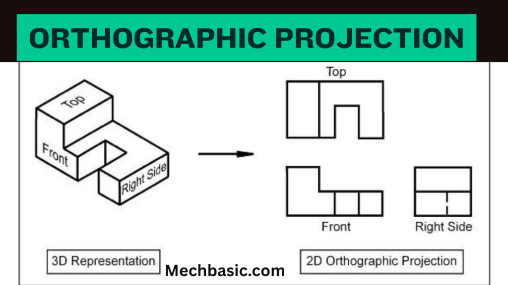
Orthographic projection is one of the most important concepts in engineering drawing. It is a method of representing a three-dimensional (3D) object on a two-dimensional (2D) drawing sheet using multiple views. These views accurately describe the shape, size, and features of an object without distortion.
Orthographic projection is the foundation of mechanical engineering, civil engineering, architecture, manufacturing, product design, and machine drawing. Every engineer, drafter, machinist, and designer must understand how to read and create orthographic drawings.
Unlike pictorial drawings, which provide a visual appearance, orthographic projections present true dimensions of an object, making them suitable for manufacturing and inspection.
What is Orthographic Projection?
Definition
Orthographic projection is a graphical method of representing a three-dimensional object using several two-dimensional views, where the projection lines are parallel to each other and perpendicular to the plane of projection.
Each view shows only one side of the object, allowing accurate representation of its dimensions and geometry.
Purpose of Orthographic Projection
Orthographic projection is used to:
- Represent 3D objects accurately on 2D drawings.
- Show the true shape and size of each feature.
- Provide complete manufacturing information.
- Eliminate ambiguity in design interpretation.
- Improve communication between engineers and manufacturers.
- Ensure precision in fabrication and inspection.
Principle of Orthographic Projection
The basic principle is that:
- The observer looks directly at one face of the object.
- Visual rays (projectors) are assumed to be parallel.
- These rays strike the projection plane at 90° (perpendicular).
- The resulting view shows the exact shape of that face.
Because the projectors are parallel, there is no perspective distortion, unlike in pictorial drawings.
Planes of Projection
Orthographic projection uses imaginary planes to obtain different views.
Vertical Plane (VP)
- Produces the Front View.
- Shows height and width.
Horizontal Plane (HP)
- Produces the Top View.
- Shows width and depth.
Profile Plane (PP)
- Produces the Side View.
- Shows height and depth.
Also Read : Planes of projection in detail.
Principal Views
A complete orthographic drawing generally consists of three principal views.
1. Front View (Elevation)
The front view is considered the most important view.
It shows:
- Height
- Width
- Major features
Usually selected as the view that best describes the object.
2. Top View (Plan)
Obtained by looking from above.
Shows:
- Width
- Depth
The top view complements the front view by revealing features not visible from the front.
3. Side View (End View)
Obtained by looking from either the right or left side.
Shows:
- Height
- Depth
Side views help clarify features hidden in the front and top views.
Additional Views
Depending on the complexity of the object, additional views may be used.
These include:
- Left-side view
- Right-side view
- Bottom view
- Rear view
- Auxiliary view
- Sectional view
- Partial view
Orthographic Projection Systems
There are two internationally accepted systems.
First Angle Projection
Definition
In first-angle projection:
- The object is located between the observer and the projection plane.
- Views are projected through the object onto the planes.
View Arrangement
- Top View → Below Front View
- Right Side View → Left of Front View
- Left Side View → Right of Front View
Countries Using First Angle Projection
- India
- United Kingdom
- Germany
- Most European countries
- Many Asian countries
It is recommended by BIS (Bureau of Indian Standards) and ISO.
Third Angle Projection
Definition
In third-angle projection:
- The projection plane lies between the observer and the object.
- Views are projected directly onto the plane.
View Arrangement
- Top View → Above Front View
- Right Side View → Right of Front View
- Left Side View → Left of Front View
Countries Using Third Angle Projection
- United States
- Canada
- Some North American industries
It is widely standardized by ASME.
Difference Between First Angle and Third Angle Projection
| Feature | First Angle Projection | Third Angle Projection |
|---|---|---|
| Object Position | Between observer and plane | Behind the projection plane |
| Top View | Below front view | Above front view |
| Right Side View | Left of front view | Right of front view |
| Left Side View | Right of front view | Left of front view |
| Common Standards | ISO, BIS | ASME |
| Common Usage | Europe, India, Asia | USA, Canada |
Rules of Orthographic Projection
Rule 1
Projection lines are always parallel.
Rule 2
Projection lines are perpendicular (90°) to the projection plane.
Rule 3
Each view represents only one side of the object.
Rule 4
All views must be properly aligned.
For example:
- Front and top views align vertically.
- Front and side views align horizontally.
Rule 5
Dimensions should not be repeated unnecessarily across different views.
Rule 6
Hidden features are represented using dashed lines.
Rule 7
Visible edges are drawn using thick continuous lines.
Rule 8
Center lines indicate the centers of holes, circles, and symmetrical features.
Rule 9
The minimum number of views should be used while fully describing the object.
Simple objects may require only one or two views, whereas complex parts often need three or more.
Rule 10
Dimensions must represent the true size of features and should not be taken by measuring the drawing.
Visualization in Orthographic Projection
Visualization is the ability to mentally convert between 2D views and the corresponding 3D object.
A beginner should:
- Identify the front view first.
- Compare the top and side views.
- Match corresponding edges and surfaces.
- Locate hidden features.
- Imagine how the views combine into a single object.
Developing visualization skills improves with practice and is essential for engineering drawing.
Reading Orthographic Drawings
Follow these steps:
Step 1
Read the title block for:
- Drawing title
- Scale
- Units
- Projection method
- Revision information
Step 2
Identify the front view.
Step 3
Locate the top and side views.
Step 4
Match common dimensions between views:
- Width is shared by front and top views.
- Height is shared by front and side views.
- Depth is shared by top and side views.
Step 5
Interpret hidden lines and center lines.
Step 6
Read all dimensions, tolerances, symbols, and notes.
Line Types Used
Visible Lines
- Thick continuous lines
- Represent visible edges
Hidden Lines
- Dashed lines
- Represent invisible edges
Center Lines
- Long-short dashed lines
- Represent centers of circles and symmetry
Dimension Lines
- Thin lines with arrowheads
- Indicate measurements
Extension Lines
- Extend from the object to dimension lines
Advantages of Orthographic Projection
- Accurate representation of objects.
- True dimensions without distortion.
- Easy to manufacture parts.
- Standardized communication.
- Supports quality inspection.
- Suitable for CAD and CNC machining.
- Widely accepted internationally.
Limitations of Orthographic Projection
- Requires multiple views.
- Beginners may find visualization difficult.
- Does not provide a realistic 3D appearance.
- Complex objects may require sectional or auxiliary views for clarity.
Applications
Orthographic projection is extensively used in:
- Mechanical engineering
- Civil engineering
- Architecture
- Manufacturing
- Aerospace
- Automotive engineering
- Product design
- CNC machining
- Robotics
- Industrial equipment design
Applications in CAD Software
Modern CAD software automatically generates orthographic views from 3D models.
Common software includes:
- AutoCAD
- SolidWorks
- CATIA
- PTC Creo
- Autodesk Inventor
- Siemens NX
- Fusion 360
These tools help ensure consistency and reduce drafting errors.
Summary Table
| Aspect | Description |
|---|---|
| Definition | Method of representing a 3D object using multiple 2D views |
| Projection Lines | Parallel and perpendicular to the projection plane |
| Main Views | Front, Top, Side |
| Projection Systems | First Angle, Third Angle |
| Primary Purpose | Accurate communication for manufacturing |
| Common Standards | ISO, BIS, ASME |
| Advantages | Precision, standardization, manufacturability |
| Common Applications | Mechanical design, manufacturing, construction, product development |
Frequently Asked Questions (FAQs)
1. What is orthographic projection?
Orthographic projection is a drawing method that represents a three-dimensional object using two-dimensional views, with projection lines that are parallel and perpendicular to the projection plane.
2. Why is orthographic projection important?
It provides accurate dimensions and shapes of objects, making it essential for manufacturing, inspection, assembly, and engineering communication.
3. What are the three principal views in orthographic projection?
The three principal views are:
- Front View (Elevation)
- Top View (Plan)
- Side View (End View)
4. What is the difference between first-angle and third-angle projection?
In first-angle projection, the top view is placed below the front view and the right-side view appears to the left of the front view. In third-angle projection, the top view is placed above the front view and the right-side view appears to the right of the front view.
5. Which projection system is used in India?
India primarily follows First Angle Projection, as recommended by BIS and aligned with ISO standards.
6. What are hidden lines?
Hidden lines are dashed lines that represent edges or features not directly visible in the current view.
7. Why are multiple views needed?
Multiple views provide a complete description of an object’s geometry, ensuring that all features can be accurately manufactured and inspected.
8. Which industries use orthographic projection?
Orthographic projection is widely used in mechanical engineering, civil engineering, architecture, manufacturing, aerospace, automotive engineering, robotics, and industrial design.
9. Can CAD software generate orthographic views automatically?
Yes. Most modern CAD software can automatically create orthographic projections from 3D models, improving accuracy and saving drafting time.
10. How can beginners improve their orthographic projection skills?
Beginners should practice sketching objects from different directions, study standard projection methods, compare 3D models with their 2D views, and solve engineering drawing exercises regularly.
Conclusion
Orthographic projection is a fundamental technique in engineering drawing that enables the accurate representation of three-dimensional objects through multiple two-dimensional views. By following standardized rules for projection, view arrangement, line conventions, and dimensioning, engineers can communicate design intent clearly and unambiguously. A solid understanding of first-angle and third-angle projection systems, combined with strong visualization skills, is essential for success in mechanical design, manufacturing, quality control, and CAD-based product development. Mastering orthographic projection provides the foundation for interpreting technical drawings and creating precise engineering documentation.
Other courses:





