
Engineering drawings use standard symbols, dimensions, and views to describe the shape and size of a component.
Beginners should learn to read orthographic views, sectional views, dimensions, and tolerances.
Understanding engineering drawings helps in manufacturing, assembly, inspection, and product design.
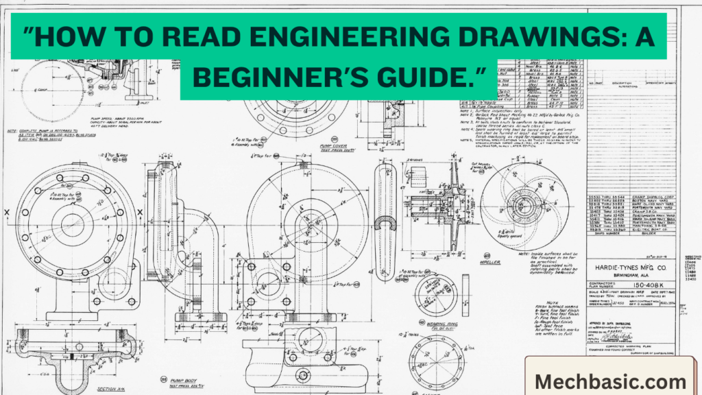
In this article:
- How to Read Engineering Drawings: A Beginner's Guide
- What is an Engineering Drawing?
- Importance of Engineering Drawings
- Types of Engineering Drawings
- Basic Elements of an Engineering Drawing
- Understanding Drawing Views
- Orthographic Projection
- Types of Lines
- Reading Dimensions
- Understanding Scale
- Symbols Commonly Used
- Tolerances
- Fits
- Surface Finish Symbols
- Geometric Dimensioning and Tolerancing (GD&T)
- Sectional Views
- Assembly Drawings
- Reading Notes
- Materials
- Standards Used
- Common Mistakes Beginners Make
- Tips for Reading Engineering Drawings
- Applications of Engineering Drawings
- Benefits of Learning to Read Engineering Drawings
- Summary Table
- Frequently Asked Questions (FAQs)
- Conclusion
How to Read Engineering Drawings: A Beginner’s Guide
Introduction
Engineering drawings are the universal language of engineers, designers, manufacturers, and technicians. They provide detailed graphical information about the size, shape, dimensions, materials, tolerances, and manufacturing requirements of a component or assembly. Every machine part, product, or structure begins as an engineering drawing before it is manufactured.
For beginners, reading engineering drawings may seem challenging because of the many lines, symbols, dimensions, and notes. However, by understanding the basic elements and following a systematic approach, anyone can learn to interpret engineering drawings accurately.
This guide explains the fundamentals of reading engineering drawings, the common symbols and standards used, and practical tips to help beginners understand technical drawings with confidence.
What is an Engineering Drawing?
Definition
An engineering drawing is a technical document that represents the shape, size, dimensions, specifications, and manufacturing details of an object using standardized graphical symbols and conventions.
It serves as a communication tool between engineers, designers, manufacturers, quality inspectors, and maintenance personnel.
Importance of Engineering Drawings
Engineering drawings are important because they:
- Communicate design ideas accurately.
- Provide manufacturing instructions.
- Ensure dimensional accuracy.
- Reduce production errors.
- Standardize product design.
- Assist in quality inspection.
- Support assembly and maintenance.
- Facilitate communication between engineering teams.
Types of Engineering Drawings
1. Detail Drawing
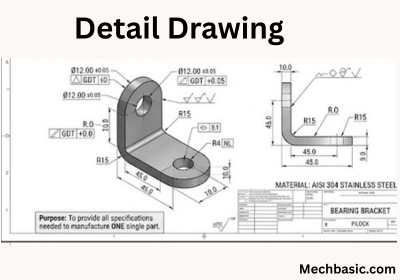
Shows all information needed to manufacture a single component.
Includes:
- Dimensions
- Material
- Surface finish
- Tolerances
- Notes
2. Assembly Drawing
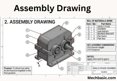
Shows how multiple components fit together.
Includes:
- Part numbers
- Assembly sequence
- Bill of Materials (BOM)
3. Sectional Drawing
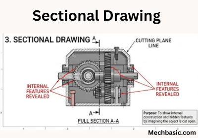
Displays internal features by imagining the object cut along a plane.
Used to reveal hidden details.
4. Exploded View Drawing
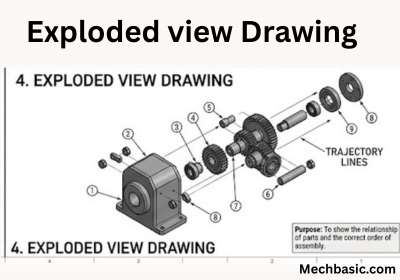
Illustrates the relative position of all components before assembly.
Common in maintenance manuals and product catalogs.
Basic Elements of an Engineering Drawing
Title Block
The title block is usually located in the bottom-right corner of the drawing.
It contains:
- Drawing title
- Drawing number
- Scale
- Date
- Revision number
- Designer’s name
- Company name
- Units
- Projection method
Always review the title block before studying the drawing.
Border
The border defines the printable area and protects the drawing contents.
Revision Block
Records changes made to the drawing during its lifecycle.
Typical information:
- Revision number
- Description of changes
- Date
- Approved by
Bill of Materials (BOM)
Used mainly in assembly drawings.
Includes:
- Part numbers
- Part names
- Material
- Quantity
Understanding Drawing Views
Engineering drawings represent three-dimensional objects using two-dimensional views.
Front View
Shows the main features of the object.
Usually selected as the most informative view.
Top View
Represents the object as viewed from above.
Right Side View
Shows the object from the right.
Left Side View
Used when necessary.
Bottom View
Shows features on the underside.
Rear View
Used for complex objects.
Isometric View
Provides a three-dimensional pictorial representation.
Useful for visualizing the object but usually not used for manufacturing dimensions.
Orthographic Projection
Orthographic projection represents different views of an object using perpendicular projection lines.
Two projection systems are commonly used:
First Angle Projection
- Widely used in Europe, India, and many Asian countries.
- The object is imagined between the observer and the projection plane.
- Views are placed opposite to the direction of observation (e.g., the top view is below the front view).
Third Angle Projection
- Common in the United States and Canada.
- The projection plane is between the observer and the object.
- Views are placed in the same direction as the observer (e.g., the top view is above the front view).
Always identify the projection symbol in the title block before interpreting the views.
Types of Lines
Different line types convey different information.
Visible Line
- Thick continuous line.
- Represents visible edges and outlines.
Hidden Line
- Dashed line.
- Represents edges not visible in the current view.
Center Line
- Long and short dashed line.
- Indicates the center of holes, circles, and symmetrical features.
Dimension Line
- Thin line with arrowheads.
- Indicates the extent and value of a dimension.
Extension Line
- Thin line extending from the object to a dimension line.
Leader Line
- Thin line pointing to a feature or note.
Cutting Plane Line
- Indicates where an object has been cut for a sectional view.
Section Line
- Thin, evenly spaced diagonal lines.
- Represent surfaces exposed by a cutting plane.
Also Read: Types of lines in detail.
Reading Dimensions
Dimensions define the size and location of features.
Common dimensions include:
- Length
- Width
- Height
- Diameter (Ø)
- Radius (R)
- Angle
- Depth
- Hole spacing
General tips:
- Read dimensions from the bottom or right side of the drawing, following the applicable drafting standard.
- Do not estimate sizes from the drawing; rely on the stated dimensions.
- Pay attention to units (millimeters, inches, etc.).
Understanding Scale
Scale indicates the relationship between the drawing size and the actual object size.
Examples:
- 1:1 – Full size
- 1:2 – Half size
- 2:1 – Double size
- 1:10 – One-tenth of actual size
The drawing scale is shown in the title block.
Symbols Commonly Used
Common symbols include:
- Ø – Diameter
- R – Radius
- ° – Angle
- ⌴ – Counterbore
- ⌵ – Countersink
- M – Metric thread
- ± – Plus/minus tolerance
- ⌀ – Circular feature indicator (often used for diameter)
Learning these symbols helps interpret drawings quickly and accurately.
Tolerances
Definition
Tolerance is the allowable variation in a dimension.
Example:
50 ± 0.02 mm
Acceptable size range:
- Minimum = 49.98 mm
- Maximum = 50.02 mm
Tolerances ensure proper fit, function, and interchangeability of parts.
Fits
Fits describe how two mating parts assemble.
Clearance Fit
Parts move freely after assembly.
Example:
Shaft rotating inside a bearing.
Transition Fit
Provides a small clearance or slight interference.
Used for accurate positioning.
Interference Fit
Requires force or heating/cooling for assembly.
Produces a rigid connection.
Surface Finish Symbols
Surface finish symbols specify the required surface quality after manufacturing.
They indicate:
- Surface roughness
- Machining requirements
- Finishing processes
Proper surface finish affects wear resistance, friction, sealing, and appearance.
Geometric Dimensioning and Tolerancing (GD&T)
GD&T uses standardized symbols to define acceptable geometric variations.
Common controls include:
- Straightness
- Flatness
- Circularity
- Cylindricity
- Parallelism
- Perpendicularity
- Position
- Concentricity
- Runout
GD&T improves manufacturing consistency and functional performance.
Sectional Views
Sectional views reveal internal features that hidden lines alone cannot clearly show.
Common types:
- Full section
- Half section
- Offset section
- Broken-out section
Assembly Drawings
Assembly drawings show:
- Component arrangement
- Fasteners
- Assembly sequence
- Part identification
- Bill of Materials
These drawings help technicians assemble products correctly.
Reading Notes
Engineering drawings often include notes such as:
- Material specification
- Heat treatment requirements
- Welding instructions
- Surface coating
- Inspection requirements
- Manufacturing standards
Always read all notes before interpreting the drawing.
Materials
Material information may include:
- Mild steel
- Stainless steel
- Aluminum alloy
- Brass
- Cast iron
- Engineering plastics
- Composite materials
Material selection affects strength, weight, corrosion resistance, and manufacturability.
Standards Used
Engineering drawings generally follow recognized standards such as:
- ISO (International Organization for Standardization)
- BIS (Bureau of Indian Standards)
- ASME Y14.5 (Geometric Dimensioning and Tolerancing)
- ANSI (American National Standards Institute)
- DIN (German Institute for Standardization)
Using standards ensures consistency and global compatibility.
Common Mistakes Beginners Make
- Ignoring the title block.
- Confusing hidden and visible lines.
- Misreading dimensions or units.
- Overlooking tolerances.
- Ignoring revision notes.
- Misinterpreting projection methods.
- Estimating measurements instead of using dimensions.
- Forgetting to read manufacturing notes.
Tips for Reading Engineering Drawings
- Start with the title block.
- Identify the projection method.
- Examine all views before focusing on details.
- Understand the different line types.
- Read all dimensions carefully.
- Check tolerances and surface finish requirements.
- Review notes and material specifications.
- Use the Bill of Materials for assembly drawings.
- Practice with simple drawings before progressing to complex assemblies.
- Refer to applicable engineering standards when interpreting symbols.
Applications of Engineering Drawings
Engineering drawings are used in:
- Mechanical engineering
- Civil engineering
- Electrical engineering
- Manufacturing
- Automotive industry
- Aerospace industry
- Shipbuilding
- Construction
- Product design
- Quality inspection
- Maintenance and repair
Benefits of Learning to Read Engineering Drawings
- Improves communication among engineering teams.
- Reduces manufacturing errors.
- Enhances quality control.
- Supports accurate assembly.
- Increases productivity.
- Builds confidence in design and manufacturing roles.
- Essential for CAD, CNC machining, and product development careers.
Summary Table
| Drawing Element | Purpose |
|---|---|
| Title Block | Provides drawing identification and general information |
| Views | Show different sides of the object |
| Lines | Represent visible edges, hidden features, centers, and dimensions |
| Dimensions | Specify size and location of features |
| Tolerances | Define acceptable dimensional variation |
| Symbols | Convey standardized manufacturing information |
| Section Views | Reveal internal features |
| Bill of Materials | Lists components in an assembly |
| Notes | Provide manufacturing and inspection instructions |
Frequently Asked Questions (FAQs)
1. What is an engineering drawing?
An engineering drawing is a standardized technical document that communicates the shape, size, dimensions, materials, and manufacturing requirements of a component or assembly.
2. Why are engineering drawings important?
They ensure accurate communication between designers, manufacturers, inspectors, and technicians, helping reduce errors and maintain product quality.
3. What is the difference between a detail drawing and an assembly drawing?
A detail drawing contains all information needed to manufacture a single part, while an assembly drawing shows how multiple parts fit and function together.
4. What are the main views in an engineering drawing?
The principal views are:
- Front view
- Top view
- Right-side view
Additional views such as left, rear, bottom, sectional, and isometric views may be included when necessary.
5. What is the purpose of dimensions?
Dimensions define the exact size, location, and geometry of features so that parts can be manufactured accurately.
6. What is tolerance?
Tolerance is the permissible variation in a specified dimension, ensuring that manufactured parts fit and function correctly despite minor manufacturing variations.
7. What is the difference between first-angle and third-angle projection?
In first-angle projection, commonly used in India and Europe, views are placed opposite the direction of observation. In third-angle projection, commonly used in North America, views are placed on the same side as the direction of observation.
8. What is GD&T?
Geometric Dimensioning and Tolerancing (GD&T) is a standardized system that uses symbols to define allowable geometric variations such as flatness, position, and perpendicularity, improving accuracy and interchangeability.
9. What software is commonly used to create engineering drawings?
Common CAD software includes:
- AutoCAD
- SolidWorks
- CATIA
- Creo
- Autodesk Inventor
- Siemens NX
10. How can beginners improve their drawing-reading skills?
Practice reading simple drawings, learn line types and symbols, understand projection methods, study dimensions and tolerances, and refer to engineering standards. Regular practice with real engineering drawings is the most effective way to build confidence and proficiency.
Conclusion
Reading engineering drawings is a fundamental skill for mechanical engineers, technicians, designers, and manufacturing professionals. By understanding title blocks, projection methods, drawing views, line types, dimensions, tolerances, symbols, and sectional views, beginners can accurately interpret technical drawings and communicate effectively within engineering teams. Mastering this skill not only improves manufacturing accuracy and quality but also forms the foundation for advanced topics such as CAD modeling, CNC machining, product design, and quality inspection. With consistent practice and familiarity with engineering standards, anyone can become proficient in reading and interpreting engineering drawings.
Other courses:





