
Fatigue failure occurs when a metal breaks due to repeated or cyclic loading, even below its yield strength.
Common causes include stress concentrations, surface defects, corrosion, and repeated vibrations.
It can be prevented by proper design, smooth surface finishing, suitable materials, and regular inspection.
In this article:
- Fatigue Failure in Metals: Causes and Prevention
- What is Fatigue Failure?
- Characteristics of Fatigue Failure
- Fatigue Loading
- Stages of Fatigue Failure
- Causes of Fatigue Failure
- Factors Affecting Fatigue Life
- Fatigue Strength
- Endurance Limit
- S-N Curve (Stress-Life Curve)
- Common Fatigue Failure Locations
- Methods of Fatigue Testing
- Prevention of Fatigue Failure
- Applications Where Fatigue is Critical
- Advantages of Fatigue Analysis
- Limitations of Fatigue Prediction
- Comparison: Static Failure vs. Fatigue Failure
- Summary Table
- Frequently Asked Questions (FAQs)
- Conclusion
Fatigue Failure in Metals: Causes and Prevention
Introduction
Fatigue failure is one of the most common and dangerous modes of failure in engineering materials, particularly metals. Unlike failures caused by a single overload, fatigue failure occurs due to repeated or cyclic loading, even when the applied stresses are well below the material’s yield strength or ultimate tensile strength. Because fatigue cracks often develop gradually and without obvious warning, fatigue failure can lead to sudden and catastrophic component failure.
Fatigue is a critical consideration in the design of aircraft, automobiles, bridges, railway systems, turbines, pressure vessels, marine structures, and industrial machinery. Engineers must understand the causes, mechanisms, and prevention methods of fatigue to ensure the safety, reliability, and long service life of engineering components.
This guide explains fatigue failure in detail, including its causes, stages, influencing factors, testing methods, prevention techniques, and real-world applications.
What is Fatigue Failure?
Definition
Fatigue failure is the progressive weakening and eventual fracture of a material caused by repeated or fluctuating stresses over time.
It occurs even when the maximum stress is lower than the material’s yield strength, provided the loading is repeated for a sufficient number of cycles.
Unlike overload failure, fatigue damage accumulates gradually until the material can no longer withstand the applied load.
Also Read : What is Fatigue Failure?
Characteristics of Fatigue Failure
Fatigue failure has several distinctive characteristics:
- Caused by cyclic or fluctuating loading.
- Can occur below the yield strength.
- Begins with microscopic cracks.
- Cracks grow progressively with each load cycle.
- Often results in sudden fracture with little warning.
- Common in components subjected to repeated motion or vibration.
Fatigue Loading
Fatigue is caused by repeated loading and unloading. Common types include:
1. Completely Reversed Loading
The stress alternates equally between tension and compression.
Examples:
- Rotating shafts
- Axles
2. Repeated (Pulsating) Loading
Stress varies between zero and a maximum value.
Examples:
- Crane hooks
- Lifting mechanisms
3. Fluctuating Loading
Stress varies between unequal maximum and minimum values.
Examples:
- Engine components
- Aircraft wings
4. Random Loading
Stress changes irregularly due to varying operating conditions.
Examples:
- Road vehicles
- Offshore structures
Stages of Fatigue Failure
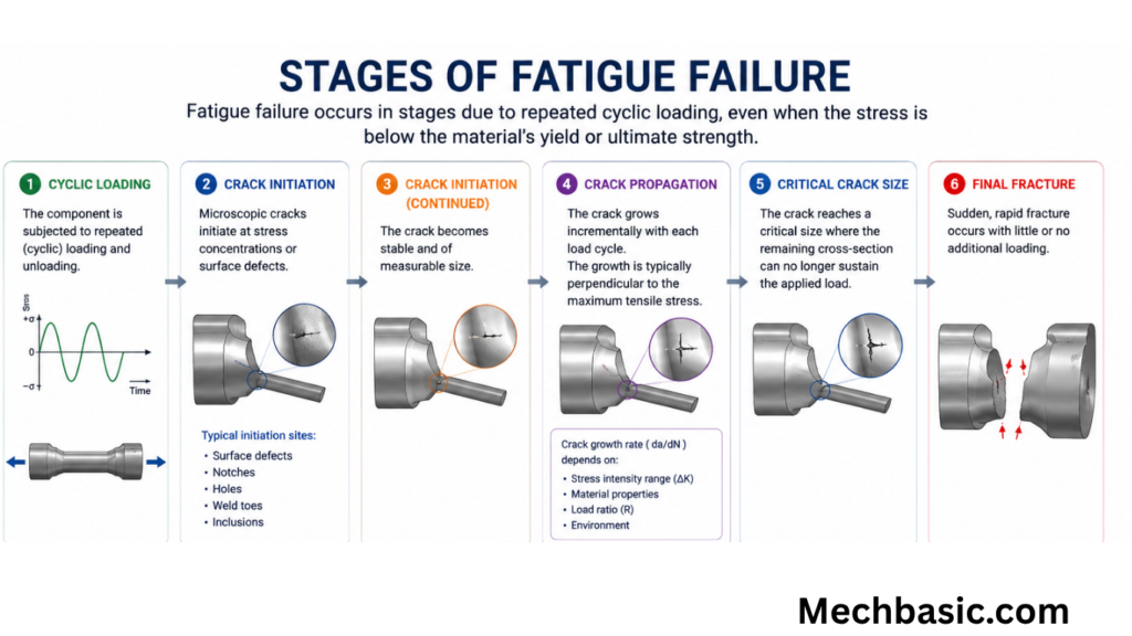
Fatigue failure generally occurs in three stages.
Stage 1: Crack Initiation
Small cracks begin to form at locations of high stress concentration, such as:
- Surface scratches
- Sharp corners
- Holes
- Weld defects
- Inclusions
- Corrosion pits
This stage often consumes a large portion of the component’s fatigue life.
Stage 2: Crack Propagation
With each load cycle, the crack grows gradually.
Characteristics include:
- Progressive crack extension
- Formation of fatigue striations
- Reduction of the effective load-bearing area
Stage 3: Final Fracture
When the remaining cross-sectional area becomes too small to support the applied load, sudden fracture occurs.
The final fracture typically appears rougher than the smooth fatigue crack region.
Causes of Fatigue Failure
Several factors contribute to fatigue failure.
1. Repeated Cyclic Loading
The primary cause of fatigue is continuous stress cycling during operation.
2. Stress Concentration
Features such as:
- Keyways
- Threads
- Holes
- Sharp corners
- Notches
increase local stresses and promote crack initiation.
3. Surface Defects
Surface imperfections act as crack initiation sites.
Examples include:
- Scratches
- Machining marks
- Corrosion pits
- Manufacturing defects
4. Poor Material Quality
Internal defects such as:
- Porosity
- Inclusions
- Segregation
- Voids
reduce fatigue strength.
5. Corrosion
Corrosive environments accelerate fatigue crack formation.
This phenomenon is called corrosion fatigue.
6. High Temperature
Elevated temperatures can reduce material strength and accelerate fatigue damage.
7. Improper Heat Treatment
Incorrect heat treatment may lower toughness or introduce residual stresses that reduce fatigue life.
8. Residual Tensile Stress
Residual tensile stresses from welding or machining can increase the likelihood of crack initiation.
Factors Affecting Fatigue Life
Fatigue life depends on:
- Stress amplitude
- Mean stress
- Material properties
- Surface finish
- Component geometry
- Temperature
- Corrosion
- Manufacturing quality
- Loading frequency
- Residual stresses
Fatigue Strength
Definition
Fatigue strength is the maximum stress a material can withstand for a specified number of load cycles without failure.
It is determined experimentally using fatigue testing.
Endurance Limit
Definition
The endurance limit (or fatigue limit) is the stress level below which some materials, such as many steels, can theoretically endure an infinite number of loading cycles without fatigue failure.
Not all metals exhibit a true endurance limit. For example, aluminum alloys generally do not have one.
S-N Curve (Stress-Life Curve)
The S-N curve (Wöhler curve) illustrates the relationship between:
- Stress amplitude (S)
- Number of cycles to failure (N)
Interpretation
- Higher stress → Fewer cycles to failure.
- Lower stress → More cycles to failure.
Engineers use S-N curves to estimate component life under cyclic loading.
Common Fatigue Failure Locations
Fatigue cracks often originate at:
- Bolt holes
- Weld joints
- Keyways
- Threads
- Gear teeth
- Shaft shoulders
- Bearing seats
- Surface scratches
Methods of Fatigue Testing
Rotating Beam Fatigue Test
A specimen is rotated while subjected to a constant bending load.
Axial Fatigue Test
The specimen experiences repeated tensile and compressive loading.
Torsional Fatigue Test
Repeated twisting loads are applied to determine torsional fatigue properties.
Bending Fatigue Test
Repeated bending loads simulate service conditions for beams and structural members.
Prevention of Fatigue Failure
Several engineering practices can significantly improve fatigue life.
1. Reduce Stress Concentration
- Use generous fillet radii.
- Avoid sharp corners.
- Minimize sudden changes in cross-section.
- Design smooth transitions.
2. Improve Surface Finish
A smoother surface reduces crack initiation sites.
Methods include:
- Polishing
- Grinding
- Superfinishing
3. Use Better Materials
Select materials with:
- High fatigue strength
- Good toughness
- Fine grain structure
- High cleanliness
4. Surface Hardening
Processes such as:
- Carburizing
- Nitriding
- Induction hardening
improve surface strength and fatigue resistance.
5. Shot Peening
Shot peening introduces beneficial compressive residual stresses at the surface, delaying crack initiation and growth.
6. Proper Heat Treatment
Correct heat treatment improves strength, toughness, and residual stress distribution.
7. Corrosion Protection
Prevent corrosion using:
- Protective coatings
- Painting
- Plating
- Lubrication
- Corrosion-resistant alloys
8. Reduce Operating Stress
Design components with adequate safety factors to minimize cyclic stress levels.
9. Regular Inspection
Use non-destructive testing (NDT) methods such as:
- Ultrasonic testing
- Magnetic particle inspection
- Dye penetrant testing
- Eddy current testing
to detect cracks before failure.
Applications Where Fatigue is Critical
Fatigue analysis is essential in:
Aerospace Engineering
- Aircraft wings
- Fuselage
- Landing gear
- Engine components
Automotive Engineering
- Crankshafts
- Connecting rods
- Axles
- Suspension springs
Civil Engineering
- Bridges
- Railway tracks
- Steel structures
Marine Engineering
- Ship hulls
- Offshore platforms
- Propeller shafts
Power Generation
- Turbine blades
- Rotating shafts
- Pressure vessels
Advantages of Fatigue Analysis
- Prevents unexpected failures.
- Improves safety.
- Extends component life.
- Reduces maintenance costs.
- Enhances design reliability.
- Optimizes material selection.
Limitations of Fatigue Prediction
- Actual loading conditions may vary.
- Material defects are difficult to predict.
- Environmental effects complicate analysis.
- Manufacturing variations influence fatigue life.
- Long-term testing is often required.
Comparison: Static Failure vs. Fatigue Failure
| Feature | Static Failure | Fatigue Failure |
|---|---|---|
| Cause | Single overload | Repeated cyclic loading |
| Stress Level | Usually above yield strength | Often below yield strength |
| Crack Growth | Rapid | Gradual |
| Warning | Often visible deformation | Little or no visible warning |
| Failure Mode | Immediate | Progressive and sudden at final stage |
Summary Table
| Aspect | Description |
|---|---|
| Fatigue Failure | Progressive failure under cyclic loading |
| Crack Initiation | Begins at stress concentration points |
| Crack Propagation | Crack grows with each load cycle |
| Final Fracture | Sudden failure after crack reaches critical size |
| Fatigue Strength | Stress level for a specified number of cycles |
| Endurance Limit | Stress below which some materials can endure infinite cycles |
| Prevention | Good design, surface treatment, material selection, inspections |
Frequently Asked Questions (FAQs)
1. What is fatigue failure?
Fatigue failure is the progressive fracture of a material caused by repeated or cyclic loading, even when the applied stress is below the material’s yield strength.
2. Why is fatigue failure dangerous?
It develops gradually with little visible warning, and once a crack reaches a critical size, the remaining material may fail suddenly and catastrophically.
3. What are the three stages of fatigue failure?
The stages are crack initiation, crack propagation, and final fracture.
4. What is the endurance limit?
The endurance limit is the stress level below which certain materials, such as many steels, can theoretically withstand an infinite number of load cycles without fatigue failure.
5. Do all metals have an endurance limit?
No. Many steels exhibit an endurance limit, whereas materials such as aluminum alloys generally do not and continue to accumulate fatigue damage with increasing load cycles.
6. What are stress concentrations?
Stress concentrations are localized regions of high stress caused by features such as holes, notches, threads, sharp corners, or sudden changes in cross-section. They are common sites for fatigue crack initiation.
7. How does shot peening improve fatigue life?
Shot peening introduces compressive residual stresses on the surface, which help delay crack initiation and slow crack growth.
8. What is an S-N curve?
An S-N (Stress-Life) curve shows the relationship between stress amplitude and the number of cycles to failure, helping engineers estimate fatigue life.
9. How can fatigue failure be prevented?
Fatigue resistance can be improved through proper design, reducing stress concentrations, improving surface finish, selecting suitable materials, applying heat treatment or surface hardening, protecting against corrosion, and performing regular inspections.
10. Where is fatigue analysis most important?
Fatigue analysis is essential in aerospace, automotive, civil, marine, railway, and power-generation industries, where components experience repeated loading throughout their service life.
Conclusion
Fatigue failure is one of the most significant failure mechanisms affecting metallic components subjected to cyclic loading. It begins with microscopic crack initiation, progresses through gradual crack growth, and ultimately results in sudden fracture. Factors such as stress concentration, surface quality, material properties, corrosion, and operating conditions strongly influence fatigue life. By applying sound engineering design principles, selecting appropriate materials, improving surface conditions, using beneficial treatments like shot peening, and conducting regular inspections, engineers can greatly reduce the risk of fatigue failure. A thorough understanding of fatigue behavior is essential for designing safe, reliable, and durable components used in critical engineering applications.
Other courses:





