
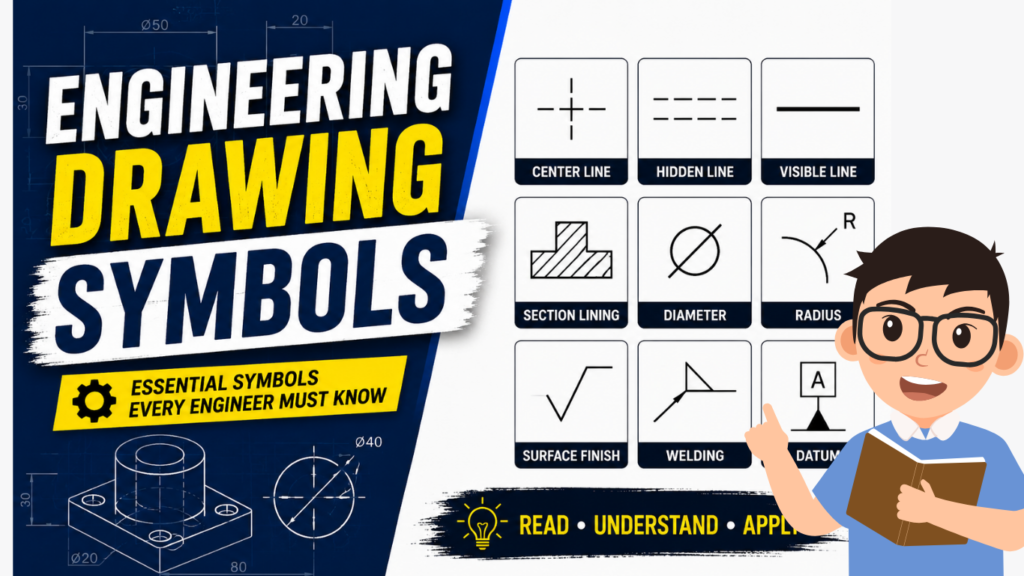
Engineering drawing symbols are standardized signs used to represent features, materials, dimensions, and manufacturing requirements.
Common symbols include diameter (Ø), radius (R), centerline, surface finish, and welding symbols.
They help ensure clear and accurate communication in technical drawings.
In this article:
Engineering Drawing Symbols
What is Engineering drawing symbol?
Engineering drawing symbols are standardized graphical marks used to convey technical information quickly and accurately. They eliminate the need for lengthy written descriptions and ensure that engineers, designers, machinists, inspectors, and manufacturers interpret drawings in the same way.
Symbols are governed by standards such as:
- ISO
- ASME
- ANSI
- BIS
Why Are Engineering Drawing Symbols Used?
Benefits
- Save drawing space
- Reduce written notes
- Improve communication
- Standardize engineering documentation
- Reduce manufacturing errors
- Speed up drawing interpretation
Types of Engineering Drawing Symbols used:
1. Dimension Symbols
These symbols specify the size and geometry of features.
Diameter Symbol
ØDefinition:
Diameter of a circle or cylindrical feature.
Example:
Ø25Means diameter = 25 mm.
Applications:
- Shafts
- Holes
- Pipes
Radius Symbol
RDefinition:
Radius of an arc or circle.
Example:
R10Means radius = 10 mm.
Spherical Radius
SRUsed for spherical surfaces.
Example:
SR50Spherical Diameter
SØIndicates diameter of a spherical object.
Depth Symbol
↧Indicates hole depth.
Example:
Ø10 ↧20Hole diameter 10 mm, depth 20 mm.
2. Geometric Dimensioning and Tolerancing (GD&T) Symbols
GD&T controls the allowable variation of features.
Straightness
—Controls straightness of lines or surfaces.
Flatness
▱Ensures a surface is flat within limits.
Circularity (Roundness)
○Controls how round a feature must be.
Cylindricity
Controls the overall cylindrical shape.
Used for:
- Shafts
- Bearings
Parallelism
∥Indicates two features must remain parallel.
Perpendicularity
⊥Indicates a 90° relationship.
Angularity
∠Controls angles other than 90°.
Position
⌖Controls the exact location of holes or features.
Concentricity
Indicates common center axes.
Symmetry
Controls symmetry about a centerline.
3. Surface Finish Symbols
These symbols specify surface quality.
Basic Surface Finish Symbol
✓Indicates a surface finish requirement exists.
Machining Required
✓—Material removal required.
Example:
Machining, grinding, milling.
Machining Not Allowed
✓○Surface must remain as produced.
Example:
Casting surface.
Roughness Value
Example:
Ra 1.6Means average roughness = 1.6 μm.
4. Welding Symbols
Used in fabrication and structural drawings.
Fillet Weld
△Most common weld type.
Used for:
- Structural steel
- Frames
Square Groove Weld
Indicates square-edge weld.
V-Groove Weld
VUsed for thicker materials.
Bevel Groove Weld
One edge beveled.
U-Groove Weld
Used for heavy sections.
Spot Weld
Circular weld at a specific point.
Seam Weld
Continuous weld along a seam.
5. Hole and Thread Symbols
Through Hole
THRUHole passes completely through.
Example:
Ø10 THRUCounterbore
⌴Flat-bottom enlargement at hole entrance.
Example:
Bolt head recess.
Countersink
⌵Conical enlargement.
Example:
Flat-head screws.
Thread Symbol
Example:
M10 × 1.5Definition:
- Metric thread
- Diameter = 10 mm
- Pitch = 1.5 mm
6. Section Symbols
Used to show internal details.
Cutting Plane Line
Indicates where the object is imagined to be cut.
Example:
A-ASection View
Shows internal features after cutting.
Hatch Lines
Thin lines showing cut material.
Common angle:
45°7. Projection Symbols
Indicate projection method.
First Angle Projection
Used mainly in:
- India
- Europe
- Asia
Object lies between observer and projection plane.
Third Angle Projection
Used mainly in:
- USA
- Canada
Projection plane lies between observer and object.
8. Material Symbols
Used in sectional views.
Steel
Parallel hatch lines.
Cast Iron
Specific hatch pattern.
Brass and Bronze
Distinct diagonal pattern.
Wood
Wood grain pattern.
Concrete
Irregular pattern.
9. Electrical Symbols
Used in electrical drawings.
Battery
Represents power source.
Switch
Represents circuit control.
Lamp
Represents light source.
Motor
Represents electric motor.
Ground
Represents earth connection.
Fuse
Represents circuit protection.
10. Fluid Power Symbols
Used in hydraulic and pneumatic systems.
Pump
Hydraulic fluid source.
Compressor
Compressed air source.
Cylinder
Linear actuator.
Valve
Controls fluid flow.
Reservoir
Stores hydraulic fluid.
Common Engineering Drawing Abbreviations
| Symbol/Abbreviation | Meaning |
|---|---|
| Ø | Diameter |
| R | Radius |
| SR | Spherical Radius |
| THRU | Through Hole |
| TYP | Typical |
| MAX | Maximum |
| MIN | Minimum |
| REF | Reference |
| PCD | Pitch Circle Diameter |
| EQ SP | Equally Spaced |
| C/L | Center Line |
| NTS | Not To Scale |
Example of Symbol Usage
Suppose a drawing contains:
Ø20 ±0.02Meaning:
- Diameter = 20 mm
- Tolerance = ±0.02 mm
Another example:
M12 × 1.75Meaning:
- Metric thread
- Diameter = 12 mm
- Pitch = 1.75 mm
Another example:
Ra 0.8Definition:
Surface roughness must not exceed 0.8 μm.
Importance of Engineering Drawing Symbols
Manufacturing
Provide machining instructions.
Inspection
Assist quality control.
Assembly
Guide fitment procedures.
Maintenance
Support repairs and servicing.
International Communication
Enable engineers worldwide to understand drawings.
Interview Questions
What is the purpose of engineering drawing symbols?
To communicate technical information clearly, accurately, and universally.
What does the symbol Ø represent?
Diameter.
What does R represent?
Radius.
What does ⊥ represent?
Perpendicularity.
What does M10 × 1.5 mean?
Metric thread of 10 mm diameter with a 1.5 mm pitch.
What is Ra in surface finish?
Average surface roughness value.
Conclusion
Engineering drawing symbols are standardized graphical representations used to communicate dimensions, tolerances, surface finishes, welds, threads, projections, materials, and other technical requirements. Understanding these symbols is essential for engineers, CAD designers, machinists, quality inspectors, and manufacturing professionals because they form the universal language of engineering drawings and ensure accurate interpretation throughout the design and production process.
Other courses:





