
Designing an engine in SolidWorks is a complex but rewarding project that requires careful planning and use of advanced SolidWorks tools. Here’s a general step-by-step guide to help you design an engine:
In this article
- Engine and its Components
- Get Technical Drawings.
- Part Modelling
- Assembly Modelling.
- Material and Appearances.
- Simulations.
- Drafting
- Render and present.
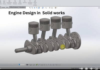
Engine and its Components
An engine is a machine or device designed to convert one form of energy into mechanical energy or motion. It is used to power various types of vehicles, machinery, and systems. Engines are typically classified based on the type of energy they use or their method of operation.
Decide the type of engine you want to design (e.g., internal combustion, electric motor, turbine).
Break down the engine into its main components:
- Piston
- Cylinder
- Crankshaft
- Connecting Rod
- Valves
- Camshaft
- Flywheel
- Block Housing
- Intake and Exhaust Systems
Get Technical Drawings.
- Obtain blueprints or technical drawings of the engine.
- Use dimensions, materials, and specifications for realistic scaling and functionality.
Use Free library tools such as grab CAD to get drawings.
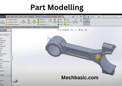
Part Modelling
- Piston: Create a simple cylinder for the piston. Add grooves for piston rings and a connecting pin hole.
- Use tools like Extruded Boss/Base, Revolve, and Fillet.
- Cylinder: Design the cylinder as a hollow tube with precise tolerances for the piston.
- Use Shell for creating hollow geometry.
- Crankshaft: Use a combination of Revolve and Extruded Boss/Base to design the shaft and counterweights.
- Add fillets to corners for stress reduction.
- Connecting Rod: Design the rod to connect the piston and crankshaft.
- Add holes at both ends for the crankshaft and piston pin.
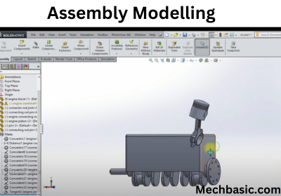
Assembly Modelling.
- Use SolidWorks Assembly to bring all parts together.
- Insert Components: Import your parts into an assembly file.
- Mate: Use mates like Concentric, Coincident, and Distance to assemble the parts accurately.
- Test the motion using Motion Analysis or Physical Dynamics to simulate the engine’s operation.
Material and Appearances
- Assign realistic materials to each component using Material Properties.
- Simulate metal alloys, plastics, or composites used in engines.
Simulations
Perform Simulations
- Use SolidWorks Simulation tools to test the engine for:
- Structural Integrity: Analyze stress and fatigue in key components.
- Thermal Analysis: Evaluate heat dissipation and cooling efficiency.
- Motion Study: Simulate the operation of moving parts.
Drafting
- Create 2D manufacturing drawings using SolidWorks Drawing.
- Include detailed dimensions, tolerances, and annotations.
- Add exploded views and a bill of materials (BOM).
Render and Present
- Use SolidWorks Visualize to create high-quality renders of your engine.
- Add realistic lighting, materials, and animations for presentations.
Tips for Success
- Plan Ahead: Understand the engine’s operation and layout before starting.
- Use Subassemblies: Group related parts (e.g., piston and connecting rod) for better management.
- Leverage Configurations: Create multiple design iterations within a single file.
- Stay Organized: Name parts and features logically to avoid confusion.