
Finite Element Analysis (FEA) is a computer-based method used to analyze the behavior of engineering components under different loads.
It divides a complex structure into small elements to calculate stress, strain, deformation, and other responses.
FEA helps engineers improve designs, reduce costs, and ensure safety and reliability before manufacturing.
In this article:
- Introduction to Finite Element Analysis (FEA) for Engineers
- What is Finite Element Analysis (FEA)?
- What is the Finite Element Method (FEM)?
- Why is FEA Important?
- Basic Principle of FEA
- Key Terminology
- Steps in Finite Element Analysis
- Types of FEA
- Material Properties Used in FEA
- Common Element Types
- Applications of FEA
- Advantages of FEA
- Limitations of FEA
- Common FEA Software
- FEA vs. Experimental Testing
- Best Practices for Accurate FEA
- Future Trends in FEA
- Summary Table
- Frequently Asked Questions (FAQs)
- Conclusion
Introduction to Finite Element Analysis (FEA) for Engineers
Introduction
Finite Element Analysis (FEA) is a powerful computer-based numerical simulation technique used to predict how engineering components and structures behave under various physical conditions such as loads, pressure, temperature, vibration, and fluid flow. It enables engineers to evaluate the strength, durability, deformation, and performance of a design before manufacturing a physical prototype.
FEA has become an essential tool in mechanical, civil, aerospace, automotive, biomedical, marine, and manufacturing engineering. By simulating real-world conditions, engineers can optimize designs, reduce development costs, improve safety, and shorten product development cycles.
This guide introduces the fundamentals of Finite Element Analysis, including its principles, workflow, types, applications, advantages, limitations, and commonly used software.
What is Finite Element Analysis (FEA)?
Definition
Finite Element Analysis (FEA) is a numerical method used to solve complex engineering problems by dividing a large structure or component into many small interconnected elements called finite elements.
Mathematical equations are solved for each element, and the results are combined to predict the behavior of the entire structure.
Also Read: What is Finite Element Analysis?
What is the Finite Element Method (FEM)?
The Finite Element Method (FEM) is the mathematical technique on which Finite Element Analysis is based.
- FEM is the mathematical method.
- FEA is the practical application of FEM using computer software.
Why is FEA Important?
FEA helps engineers:
- Predict structural performance before manufacturing.
- Reduce the number of physical prototypes.
- Improve product safety.
- Optimize material usage.
- Reduce development costs.
- Identify design weaknesses.
- Increase product reliability.
- Accelerate product development.
Basic Principle of FEA
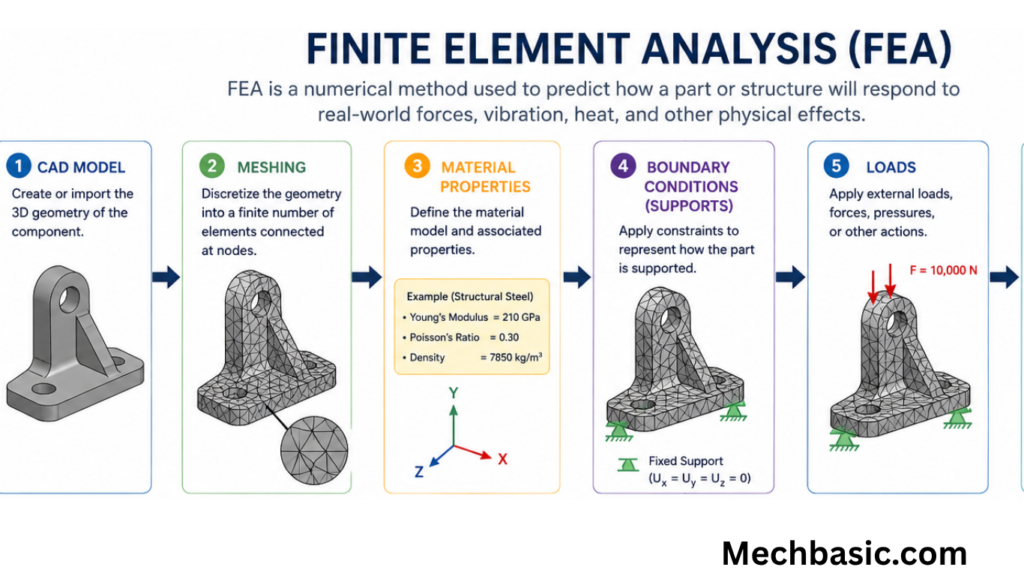
Instead of analyzing an entire structure as one complex body, FEA divides it into many small, simple pieces called elements.
The analysis process consists of:
- Dividing the structure into elements.
- Connecting elements at nodes.
- Applying material properties.
- Applying loads and boundary conditions.
- Solving mathematical equations.
- Combining element results to obtain the overall response.
Key Terminology
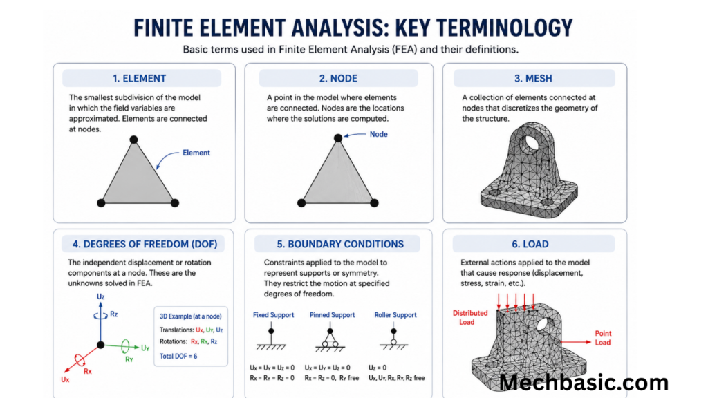
1. Element
An element is a small portion of the structure used in numerical calculations.
Common element types include:
- Line elements
- Triangular elements
- Quadrilateral elements
- Tetrahedral elements
- Hexahedral (brick) elements
2. Node
A node is a point where elements are connected.
Nodes store information such as:
- Displacement
- Rotation
- Temperature
- Stress
- Strain
3. Mesh
A mesh is the complete network of interconnected elements covering the model.
Mesh Quality
Good mesh quality improves:
- Accuracy
- Stability
- Solution convergence
However, finer meshes increase computational time and memory usage.
4. Degrees of Freedom (DOF)
Degrees of Freedom describe the independent movements permitted at a node.
Examples include:
- Translation along the X-axis
- Translation along the Y-axis
- Translation along the Z-axis
- Rotation about the X-axis
- Rotation about the Y-axis
- Rotation about the Z-axis
5. Boundary Conditions
Boundary conditions define how the model is constrained.
Examples:
- Fixed support
- Roller support
- Hinged support
- Symmetry conditions
6. Loads
Typical loads applied in FEA include:
- Forces
- Pressure
- Torque
- Gravity
- Temperature
- Acceleration
- Wind loads
- Fluid pressure
Steps in Finite Element Analysis
Step 1: Create Geometry
Develop a 2D or 3D CAD model of the component.
Step 2: Define Material Properties
Specify material characteristics such as:
- Young’s Modulus
- Poisson’s Ratio
- Density
- Yield Strength
- Thermal Conductivity
- Coefficient of Thermal Expansion
Step 3: Mesh Generation
Divide the geometry into finite elements.
A finer mesh generally increases accuracy but also increases computation time.
Step 4: Apply Boundary Conditions
Specify supports and constraints.
Examples:
- Fixed edges
- Pinned joints
- Symmetry planes
Step 5: Apply Loads
Apply operating conditions such as:
- External forces
- Pressure
- Thermal loads
- Rotational speed
Step 6: Solve
The FEA software assembles and solves thousands or millions of equations describing the system’s behavior.
Step 7: Post-Processing
Analyze the results, including:
- Stress distribution
- Strain distribution
- Displacement
- Factor of Safety
- Temperature
- Deformation
- Natural frequencies
Types of FEA
1. Structural Analysis
Evaluates:
- Stress
- Strain
- Deformation
- Factor of Safety
Applications:
- Machine components
- Bridges
- Buildings
2. Thermal Analysis
Studies temperature distribution and heat transfer.
Applications:
- Engines
- Electronics
- Heat exchangers
3. Dynamic Analysis
Analyzes structures subjected to time-dependent loads.
Examples:
- Earthquakes
- Vibrations
- Impact loads
4. Modal Analysis
Determines:
- Natural frequencies
- Mode shapes
Applications:
- Aircraft
- Turbines
- Machine tools
5. Buckling Analysis
Predicts structural instability under compressive loads.
Applications:
- Columns
- Thin plates
- Aerospace structures
6. Fatigue Analysis
Estimates component life under repeated loading.
Applications:
- Crankshafts
- Aircraft wings
- Suspension systems
7. Nonlinear Analysis
Used when materials or loading conditions are nonlinear.
Examples:
- Plastic deformation
- Large deformations
- Contact problems
Material Properties Used in FEA
Common material inputs include:
- Young’s Modulus
- Poisson’s Ratio
- Density
- Yield Strength
- Ultimate Tensile Strength
- Thermal Conductivity
- Specific Heat Capacity
- Thermal Expansion Coefficient
Accurate material data are essential for reliable simulation results.
Common Element Types
| Element Type | Typical Application |
|---|---|
| Beam Elements | Frames, bridges, shafts |
| Shell Elements | Aircraft skins, vehicle bodies |
| Solid Elements | Machine parts, castings |
| Plate Elements | Flat structural members |
| Tetrahedral Elements | Complex 3D geometries |
| Hexahedral Elements | High-accuracy structural models |
Applications of FEA
Mechanical Engineering
- Gear design
- Shaft analysis
- Pressure vessels
- Springs
- Bearings
Civil Engineering
- Buildings
- Bridges
- Dams
- Towers
- Foundations
Aerospace Engineering
- Aircraft wings
- Fuselage
- Landing gear
- Rocket structures
Automotive Engineering
- Chassis
- Suspension
- Brake systems
- Engine components
- Crash simulations
Biomedical Engineering
- Artificial joints
- Bone implants
- Dental implants
- Prosthetic devices
Manufacturing
- Metal forming
- Injection molding
- Casting
- Welding simulations
Advantages of FEA
- Reduces physical prototype requirements.
- Lowers development costs.
- Improves product quality.
- Predicts failure locations.
- Optimizes designs.
- Saves development time.
- Enhances product safety.
- Supports complex geometries.
- Evaluates multiple loading conditions.
- Enables virtual testing.
Limitations of FEA
- Accuracy depends on mesh quality.
- Incorrect boundary conditions produce inaccurate results.
- Requires accurate material properties.
- Complex analyses demand high computing power.
- Results require engineering interpretation.
- Software licenses can be expensive.
Common FEA Software
Popular FEA software packages include:
- ANSYS
- Abaqus
- SolidWorks Simulation
- COMSOL Multiphysics
- MSC Nastran
- Autodesk Inventor Nastran
- Altair HyperWorks (OptiStruct)
- LS-DYNA
- Siemens Simcenter 3D
- Fusion 360 Simulation
FEA vs. Experimental Testing
| Feature | Finite Element Analysis | Experimental Testing |
|---|---|---|
| Cost | Lower after software investment | Higher due to prototypes |
| Time | Faster | Slower |
| Accuracy | High with proper modeling | High when well executed |
| Physical Prototype | Not required initially | Required |
| Design Changes | Easy to implement | Expensive and time-consuming |
| Real-world Validation | Requires experimental confirmation | Direct measurement |
Best Practices for Accurate FEA
- Use accurate material properties.
- Create high-quality meshes.
- Refine the mesh in high-stress regions.
- Apply realistic loads and constraints.
- Check for solution convergence.
- Validate simulation results with experiments or analytical calculations.
- Review assumptions and simplify the model only where appropriate.
Future Trends in FEA
Modern FEA is advancing with:
- Artificial Intelligence (AI)-assisted optimization
- Cloud-based simulation
- Digital twins
- Generative design
- Topology optimization
- High-performance computing (HPC)
- Real-time simulation
- Multi-physics analysis
- Machine learning-assisted modeling
These technologies are making simulations faster, more accurate, and more integrated into product development.
Summary Table
| Aspect | Description |
|---|---|
| Finite Element Analysis (FEA) | Numerical simulation technique for engineering analysis |
| Finite Element Method (FEM) | Mathematical method behind FEA |
| Element | Small subdivision of the model |
| Node | Connection point between elements |
| Mesh | Collection of finite elements |
| Boundary Conditions | Constraints applied to the model |
| Loads | External forces, pressure, temperature, etc. |
| Post-Processing | Interpretation of simulation results |
Frequently Asked Questions (FAQs)
1. What is Finite Element Analysis (FEA)?
FEA is a computer-based numerical method used to predict how engineering components respond to loads, pressure, temperature, vibration, and other physical effects.
2. What is the difference between FEM and FEA?
The Finite Element Method (FEM) is the mathematical technique, while Finite Element Analysis (FEA) is the practical implementation of FEM using computer software.
3. What is a finite element?
A finite element is a small subdivision of a larger structure used in numerical calculations. Together, many elements form a mesh that approximates the behavior of the entire model.
4. Why is meshing important in FEA?
Meshing divides the model into elements for analysis. A well-designed mesh improves solution accuracy, while poor mesh quality can lead to inaccurate or unstable results.
5. What are boundary conditions?
Boundary conditions define how the model is supported or constrained and specify how it interacts with its surroundings during analysis.
6. What types of analyses can be performed using FEA?
Common analyses include structural, thermal, dynamic, modal, buckling, fatigue, and nonlinear analyses.
7. Which industries use FEA?
FEA is widely used in mechanical, civil, aerospace, automotive, biomedical, marine, and manufacturing industries for design verification and optimization.
8. Is FEA always accurate?
FEA can provide highly accurate predictions when appropriate material properties, mesh quality, boundary conditions, and loading assumptions are used. Validation with experimental testing is recommended for critical applications.
9. What are the main advantages of FEA?
FEA reduces prototype costs, shortens development time, identifies design weaknesses, optimizes components, and improves product safety and reliability.
10. What software is commonly used for FEA?
Widely used FEA software includes ANSYS, Abaqus, SolidWorks Simulation, COMSOL Multiphysics, MSC Nastran, Autodesk Inventor Nastran, Altair HyperWorks, LS-DYNA, Siemens Simcenter 3D, and Fusion 360 Simulation.
Conclusion
Finite Element Analysis (FEA) is one of the most important tools in modern engineering, enabling engineers to simulate and evaluate the behavior of components and structures before physical manufacturing. By dividing complex geometries into finite elements, FEA provides detailed insights into stress, strain, deformation, temperature distribution, vibration, and fatigue performance. It helps reduce development costs, improve product quality, optimize designs, and enhance safety across a wide range of industries. Although the accuracy of FEA depends on proper modeling, material data, mesh quality, and boundary conditions, it remains an indispensable technology for designing reliable, efficient, and innovative engineering systems.
Other courses:





