
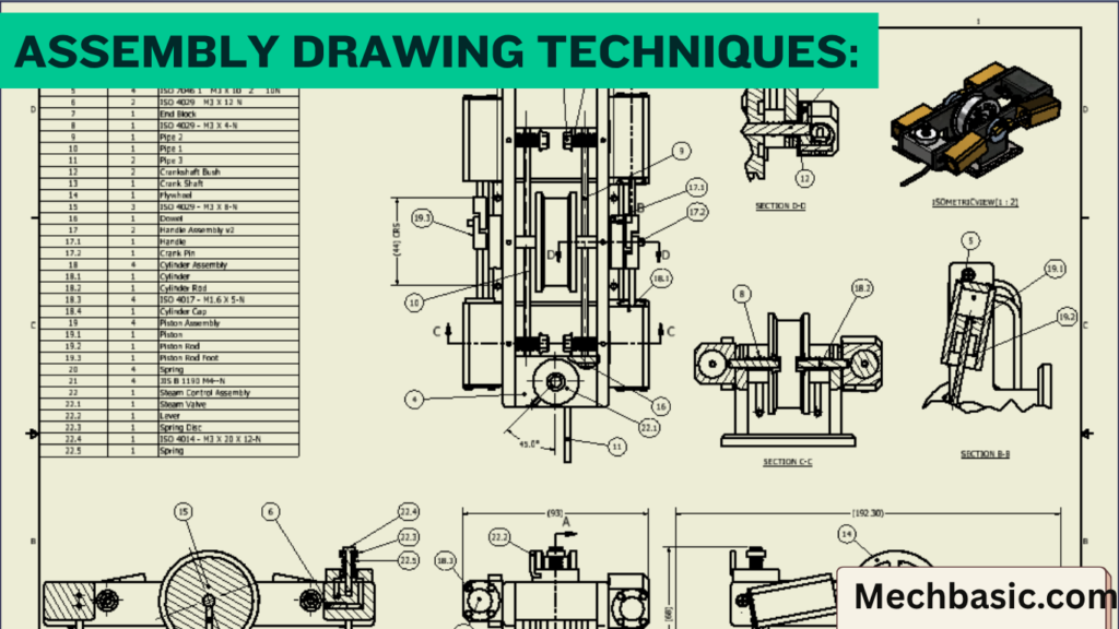
Assembly drawings show how individual parts fit together to form a complete product.
Use clear views, proper dimensions, labels, and part numbers to make the blueprint easy to understand.
Well-prepared assembly drawings improve manufacturing, assembly, maintenance, and quality control.
In this article:
- Assembly Drawing Techniques: Tips for Clear Blueprints
- What is an Assembly Drawing?
- Purpose of an Assembly Drawing
- Types of Assembly Drawings
- Basic Elements of an Assembly Drawing
- Orthographic Views
- Sectional Views
- Exploded Views
- Dimensioning in Assembly Drawings
- Tolerances
- Line Types
- Choosing the Correct Scale
- Tips for Creating Clear Blueprints
- Common Mistakes to Avoid
- CAD Software for Assembly Drawings
- Applications of Assembly Drawings
- Advantages of Well-Designed Assembly Drawings
- Future Trends
- Summary Table
- Frequently Asked Questions (FAQs)
- Conclusion
Assembly Drawing Techniques: Tips for Clear Blueprints
Introduction
An assembly drawing is a technical drawing that shows how individual parts fit and work together to form a complete product or machine. Unlike a detail drawing, which provides manufacturing information for a single component, an assembly drawing focuses on the relationship, position, orientation, and method of assembling multiple parts.
Assembly drawings are essential in industries such as mechanical engineering, automotive, aerospace, manufacturing, construction, robotics, and industrial equipment design. They help engineers, technicians, manufacturers, and maintenance personnel understand how components are assembled, inspected, serviced, and disassembled.
Creating clear assembly drawings reduces production errors, improves communication, shortens assembly time, and ensures products are built correctly.
What is an Assembly Drawing?
Definition
An assembly drawing is a graphical representation of a complete product that illustrates how individual components are positioned and connected to form a functional assembly.
It provides sufficient information for assembly, installation, maintenance, and inspection without showing all manufacturing details of each individual part.
Purpose of an Assembly Drawing
Assembly drawings are used to:
- Show how parts fit together.
- Guide assembly operations.
- Communicate design intent.
- Assist manufacturing and quality control.
- Support maintenance and repairs.
- Identify individual components.
- Reduce assembly errors.
- Provide reference for service manuals.
Types of Assembly Drawings
1. General Assembly Drawing
Shows the complete assembled product and the relative position of all components.
Applications:
- Machines
- Industrial equipment
- Automotive assemblies
2. Exploded Assembly Drawing
Displays components separated along their assembly paths while maintaining their relative positions.
Applications:
- User manuals
- Maintenance guides
- Spare parts catalogs
Advantages
- Easy identification of components.
- Simplifies assembly and disassembly.
- Improves maintenance documentation.
3. Installation Assembly Drawing
Shows how a machine or component is installed in its working environment.
Applications:
- Pumps
- Motors
- HVAC systems
- Industrial machinery
4. Sub-Assembly Drawing
Illustrates a group of related components that form part of a larger assembly.
Examples:
- Gearbox assembly
- Brake assembly
- Bearing housing assembly
5. Schematic Assembly Drawing
Uses simplified symbols instead of detailed shapes to represent components.
Applications:
- Hydraulic systems
- Pneumatic systems
- Electrical systems
Basic Elements of an Assembly Drawing
1. Title Block
Typically located in the bottom-right corner.
Contains:
- Drawing title
- Drawing number
- Revision number
- Scale
- Units
- Company name
- Designer’s name
- Date
- Projection method
2. Bill of Materials (BOM)
Lists every component in the assembly.
Typical information includes:
- Item number
- Part name
- Quantity
- Material
- Part number
- Remarks
The BOM helps procurement, inventory management, and assembly teams identify required parts.
3. Balloon Numbers
Balloon numbers connect components in the drawing to corresponding items in the BOM.
Guidelines
- Number each unique component only once.
- Place balloons outside the object whenever possible.
- Avoid crossing leader lines.
- Keep numbering logical and sequential.
4. Leader Lines
Leader lines connect balloons or notes to the relevant parts.
Good practices include:
- Use thin continuous lines.
- Keep them short and uncluttered.
- Avoid intersecting other lines.
5. Notes
Assembly drawings often include notes such as:
- Torque specifications
- Lubrication requirements
- Welding instructions
- Assembly sequence
- Safety warnings
- Special handling instructions
Also Read: Elements of Assembly Drawing in detail.
Orthographic Views
Most assembly drawings use orthographic projection.
Common views include:
- Front view
- Top view
- Right-side view
- Sectional view
- Auxiliary view
- Isometric view (for visualization)
Only the views necessary to clearly communicate the assembly should be included.
Sectional Views
Sectional views expose internal components that would otherwise be hidden.
Benefits
- Clarify internal arrangements.
- Reduce excessive hidden lines.
- Improve readability.
Common sectional views:
- Full section
- Half section
- Offset section
- Broken-out section
Exploded Views
Exploded views separate components along their assembly direction while maintaining alignment.
Benefits
- Simplify assembly procedures.
- Improve maintenance documentation.
- Clearly show component relationships.
- Help identify missing parts.
Dimensioning in Assembly Drawings
Assembly drawings should include only dimensions necessary for:
- Assembly
- Installation
- Overall size
- Functional relationships
Avoid repeating manufacturing dimensions that belong in detail drawings.
Common dimensions include:
- Overall length
- Overall width
- Overall height
- Mounting hole locations
- Center distances
- Clearances
Tolerances
Only functional tolerances should be included on assembly drawings.
Typical examples:
- Shaft-bearing fits
- Hole alignment
- Bolt-hole spacing
- Assembly clearances
Detailed manufacturing tolerances are specified in part drawings.
Line Types
Use standard line conventions for clarity.
Visible Lines
Represent visible edges.
Hidden Lines
Represent concealed features.
Center Lines
Indicate symmetry and centers of holes or shafts.
Section Lines
Show surfaces cut by a sectional plane.
Leader Lines
Connect notes and balloons to components.
Choosing the Correct Scale
Select a scale that clearly shows all features.
Common scales:
- 1:1 (Full size)
- 1:2 (Half size)
- 2:1 (Enlarged)
- 1:5
- 1:10
Complex assemblies may require enlarged detail views for small components.
Tips for Creating Clear Blueprints
1. Select the Best Front View
Choose the view that shows the maximum number of features with the fewest hidden lines.
2. Minimize Hidden Lines
Use sectional views instead of excessive hidden lines to improve readability.
3. Keep the Drawing Uncluttered
Avoid unnecessary dimensions, notes, and duplicate information.
4. Organize Balloon Numbers
Arrange balloons systematically around the drawing.
Maintain consistent spacing.
5. Use Standard Symbols
Follow recognized standards for:
- Welding
- Surface finish
- GD&T
- Threads
- Fasteners
6. Follow Engineering Standards
Use standards such as:
- ISO
- BIS
- ASME Y14 series
- ANSI
7. Maintain Proper Alignment
Ensure all orthographic views are correctly aligned to avoid confusion.
8. Include Complete BOM
Verify that every component shown is listed in the Bill of Materials.
9. Add Assembly Instructions
Include important notes for:
- Tightening sequence
- Lubrication
- Orientation
- Safety precautions
10. Review Before Release
Check for:
- Missing components
- Incorrect numbering
- Dimension errors
- BOM consistency
- Revision accuracy
Common Mistakes to Avoid
- Overcrowding the drawing.
- Omitting item numbers.
- Incorrect BOM references.
- Missing assembly notes.
- Excessive hidden lines.
- Poor leader-line placement.
- Duplicate dimensions.
- Inconsistent scales.
- Unclear sectional views.
CAD Software for Assembly Drawings
Modern CAD software simplifies the creation of assembly drawings.
Popular software includes:
- AutoCAD
- SolidWorks
- CATIA
- PTC Creo
- Autodesk Inventor
- Siemens NX
- Fusion 360
These programs can automatically generate:
- Assembly views
- Exploded views
- BOM tables
- Balloon numbering
- Sectional views
Applications of Assembly Drawings
Assembly drawings are widely used in:
- Mechanical engineering
- Automotive manufacturing
- Aerospace engineering
- Industrial machinery
- Robotics
- Medical devices
- Consumer products
- Construction equipment
- Agricultural machinery
- Marine engineering
Advantages of Well-Designed Assembly Drawings
- Improve communication between teams.
- Reduce manufacturing and assembly errors.
- Speed up production.
- Simplify maintenance and servicing.
- Improve quality control.
- Reduce assembly time.
- Support training of technicians.
- Ensure consistent product assembly.
Future Trends
Modern assembly drawings increasingly incorporate:
- 3D CAD models
- Model-Based Definition (MBD)
- Digital twins
- Interactive assembly instructions
- Augmented Reality (AR) for assembly guidance
- Cloud-based collaboration
- Automated BOM generation
- AI-assisted drawing validation
These technologies improve accuracy, collaboration, and efficiency throughout the product lifecycle.
Summary Table
| Element | Purpose |
|---|---|
| Title Block | Identifies the drawing and provides general information |
| Bill of Materials (BOM) | Lists all components and quantities |
| Balloon Numbers | Link components to the BOM |
| Orthographic Views | Show the assembly from different directions |
| Sectional Views | Reveal internal features |
| Exploded Views | Illustrate assembly sequence and relationships |
| Dimensions | Provide overall and installation sizes |
| Notes | Include assembly, safety, and maintenance instructions |
| Standard Symbols | Communicate technical requirements consistently |
Frequently Asked Questions (FAQs)
1. What is an assembly drawing?
An assembly drawing is a technical drawing that shows how individual parts fit together to form a complete product or machine.
2. What is the difference between a detail drawing and an assembly drawing?
A detail drawing provides manufacturing information for a single component, while an assembly drawing shows the relationship, position, and method of assembling multiple components.
3. What is a Bill of Materials (BOM)?
A Bill of Materials is a table that lists all components in an assembly, including their item numbers, names, quantities, materials, and part numbers.
4. Why are exploded views used?
Exploded views clearly illustrate how components fit together, making assembly, maintenance, troubleshooting, and spare parts identification easier.
5. Should assembly drawings include all manufacturing dimensions?
No. Assembly drawings should include only dimensions required for assembly, installation, and overall fit. Detailed manufacturing dimensions belong in individual part drawings.
6. What is the purpose of balloon numbers?
Balloon numbers identify components on the drawing and correspond to entries in the Bill of Materials, making it easy to locate and identify parts.
7. Which projection method is commonly used for assembly drawings?
Assembly drawings typically use orthographic projection, following either first-angle or third-angle projection standards, depending on regional or organizational requirements.
8. Which CAD software is commonly used to create assembly drawings?
Popular CAD software includes AutoCAD, SolidWorks, CATIA, PTC Creo, Autodesk Inventor, Siemens NX, and Fusion 360.
9. What are the benefits of a clear assembly drawing?
Clear assembly drawings reduce errors, improve communication, speed up production, simplify maintenance, enhance quality control, and ensure correct product assembly.
10. What are the latest trends in assembly documentation?
Modern trends include 3D model-based definition (MBD), digital twins, augmented reality (AR) assembly guidance, cloud collaboration, AI-assisted drawing validation, and automated BOM generation.
Conclusion
Assembly drawings are an essential part of engineering documentation, providing a clear visual representation of how individual components combine to form a complete product. By using proper orthographic views, exploded views, sectional views, well-organized BOMs, balloon numbering, and standardized symbols, engineers can create clear and effective blueprints that improve manufacturing accuracy, assembly efficiency, and maintenance. Following established engineering standards and best practices ensures that assembly drawings communicate design intent effectively while reducing errors and supporting the entire product lifecycle.
Other courses:





