
GD&T (Geometric Dimensioning and Tolerancing) uses standard symbols to define the size, shape, orientation, and position of features.
Common GD&T symbols include straightness, flatness, circularity, parallelism, perpendicularity, and position.
These symbols ensure accurate manufacturing, proper assembly, and consistent product quality.
In this article:
- Crucial Geometric Dimensioning and Tolerancing (GD&T) Symbols
- What is GD&T?
- Why is GD&T Important?
- Categories of GD&T Symbols
- 1. Form Controls
- 2. Profile Controls
- 3. Orientation Controls
- 4. Location Controls
- 5. Runout Controls
- Datum System
- Feature Control Frame (FCF)
- Material Condition Modifiers
- Benefits of Using GD&T
- Applications of GD&T
- Common Mistakes When Using GD&T
- Summary Table
- Frequently Asked Questions (FAQs)
- Conclusion
Crucial Geometric Dimensioning and Tolerancing (GD&T) Symbols
Introduction
Geometric Dimensioning and Tolerancing (GD&T) is a standardized system used in engineering drawings to define the allowable variation in the geometry of manufactured parts. Unlike traditional dimensioning, which specifies only size and location, GD&T controls the shape, orientation, position, and runout of features, ensuring that parts fit, function, and assemble correctly.
GD&T is widely used in industries such as automotive, aerospace, manufacturing, robotics, medical devices, and precision engineering. It is standardized by ASME Y14.5 and ISO GPS (Geometrical Product Specifications) standards.
Learning GD&T symbols is essential for mechanical engineers, designers, CNC programmers, machinists, and quality inspectors.
What is GD&T?
Definition
Geometric Dimensioning and Tolerancing (GD&T) is a symbolic language used on engineering drawings to communicate the allowable geometric variation of features, ensuring consistent manufacturing and inspection.
Why is GD&T Important?
GD&T helps to:
- Improve product quality.
- Ensure proper assembly of parts.
- Reduce manufacturing costs.
- Increase interchangeability.
- Simplify inspection processes.
- Improve communication between design and manufacturing teams.
- Minimize production errors.
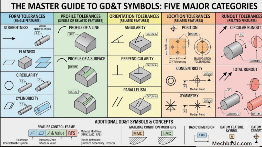
Categories of GD&T Symbols
GD&T symbols are grouped into five major categories:
- Form Controls
- Profile Controls
- Orientation Controls
- Location Controls
- Runout Controls
There are 14 fundamental GD&T symbols recognized by ASME Y14.5.
1. Form Controls
Form controls define the shape of a feature without referencing a datum.
1. Straightness
Purpose
Controls the straightness of a line or axis.
Applications
- Shafts
- Guide rails
- Machine slides
Advantages
- Reduces bending.
- Improves alignment.
- Ensures smooth motion.
2. Flatness
Purpose
Controls the flatness of a surface.
Applications
- Machine bases
- Mounting plates
- Flanges
Benefits
- Better sealing.
- Stable mounting.
- Uniform contact.
3. Circularity (Roundness)
Purpose
Ensures every cross-section of a cylindrical feature is circular.
Applications
- Bearings
- Shafts
- Bushings
- Rollers
4. Cylindricity
Purpose
Controls the overall cylindrical shape by combining straightness, circularity, and taper requirements.
Applications
- Hydraulic cylinders
- Pistons
- Precision shafts
2. Profile Controls
Profile controls regulate the contour of surfaces or lines.
5. Profile of a Line
Purpose
Controls the shape of a two-dimensional cross-section.
Applications
- Turbine blades
- Cam profiles
- Curved machine parts
6. Profile of a Surface
Purpose
Controls the shape of an entire three-dimensional surface.
Applications
- Automotive body panels
- Aircraft wings
- Plastic molded components
3. Orientation Controls
Orientation controls define the angular relationship between features and datums.
7. Parallelism
Purpose
Ensures a feature remains parallel to a specified datum.
Applications
- Machine guideways
- Sliding mechanisms
- Parallel plates
Benefits
- Smooth motion.
- Accurate assembly.
- Reduced wear.
8. Perpendicularity
Purpose
Ensures a feature is at exactly 90° to a datum.
Applications
- Machine frames
- Brackets
- Base plates
9. Angularity
Purpose
Controls a feature at a specified angle other than 90°.
Applications
- Tapered components
- Angled supports
- Beveled surfaces
4. Location Controls
Location controls specify the precise position of features relative to datums.
10. Position (True Position)
Purpose
Defines the exact allowable location of holes, pins, slots, or other features.
Applications
- Bolt holes
- Bearing seats
- Dowel pin holes
Importance
One of the most frequently used GD&T controls because it ensures proper assembly and interchangeability.
11. Concentricity
Purpose
Ensures that the median points of a feature are aligned with the datum axis.
Applications
- Rotating shafts
- Bearings
- Precision machine components
Note
Concentricity is difficult to measure and is less commonly used in modern designs. Position or runout controls are often preferred.
12. Symmetry
Purpose
Ensures features are equally spaced about a datum plane.
Applications
- Slots
- Grooves
- Symmetrical brackets
Note
Symmetry is also less commonly specified today because profile or position controls can often achieve the desired functional requirement more effectively.
5. Runout Controls
Runout controls manage variation during rotation.
13. Circular Runout
Purpose
Controls variation in a single circular cross-section while the part rotates.
Applications
- Rotating shafts
- Brake discs
- Rollers
Benefits
- Reduces vibration.
- Improves rotational accuracy.
- Enhances surface finish.
14. Total Runout
Purpose
Controls variation across the entire rotating surface.
Applications
- Turbine shafts
- Precision spindles
- Rotors
Benefits
- Minimizes wobble.
- Improves balance.
- Increases bearing life.
Datum System
What is a Datum?
A datum is a theoretically exact reference point, axis, or plane used to establish the location and orientation of other features.
Datums provide a consistent basis for manufacturing and inspection.
Types of Datums
- Primary Datum
- Secondary Datum
- Tertiary Datum
Example:
- Datum A – Bottom surface
- Datum B – Side surface
- Datum C – Hole centerline
Feature Control Frame (FCF)
The Feature Control Frame is the rectangular box that communicates GD&T requirements on a drawing.
It typically contains:
- GD&T symbol
- Tolerance value
- Diameter symbol (if applicable)
- Datum references
Example:
Position | Ø0.10 | A | B | C
This indicates that the feature must lie within a cylindrical tolerance zone of 0.10 mm relative to datums A, B, and C.
Material Condition Modifiers
Material condition modifiers refine how tolerances apply.
Maximum Material Condition (MMC)
Applies when the feature contains the maximum amount of material.
Example:
- Largest shaft diameter
- Smallest hole diameter
MMC allows bonus tolerance as material is removed.
Least Material Condition (LMC)
Applies when the feature contains the least amount of material.
Example:
- Smallest shaft
- Largest hole
Useful for maintaining minimum wall thickness.
Also Read: Material Condition Modifiers in detail
Regardless of Feature Size (RFS)
The specified tolerance remains the same regardless of the actual size of the feature.
Benefits of Using GD&T
- Better product functionality.
- Improved interchangeability of parts.
- Reduced manufacturing costs.
- Simplified inspection.
- Enhanced communication.
- Greater design flexibility.
- Improved assembly accuracy.
- Reduced scrap and rework.
Applications of GD&T
GD&T is widely used in:
- Automotive engineering
- Aerospace engineering
- CNC machining
- Robotics
- Medical devices
- Heavy machinery
- Precision manufacturing
- Defense equipment
- Industrial automation
Common Mistakes When Using GD&T
- Selecting incorrect datums.
- Applying unnecessary tight tolerances.
- Confusing form and position controls.
- Overusing concentricity or symmetry.
- Ignoring functional requirements.
- Misinterpreting feature control frames.
Summary Table
| GD&T Category | Symbol Name | Purpose | Typical Applications |
|---|---|---|---|
| Form | Straightness | Controls straightness of a line or axis | Shafts, guide rails |
| Form | Flatness | Controls surface flatness | Base plates, flanges |
| Form | Circularity | Controls roundness | Bearings, rollers |
| Form | Cylindricity | Controls cylindrical shape | Pistons, cylinders |
| Profile | Profile of a Line | Controls 2D contour | Cam profiles |
| Profile | Profile of a Surface | Controls 3D contour | Aircraft panels |
| Orientation | Parallelism | Controls parallel relationship | Guideways |
| Orientation | Perpendicularity | Controls 90° relationship | Brackets |
| Orientation | Angularity | Controls specified angles | Tapered parts |
| Location | Position | Controls feature location | Holes, pins |
| Location | Concentricity | Aligns median points | Rotating shafts |
| Location | Symmetry | Controls equal spacing | Slots, grooves |
| Runout | Circular Runout | Controls rotation at one section | Brake discs |
| Runout | Total Runout | Controls rotation over the full surface | Spindles, rotors |
Frequently Asked Questions (FAQs)
1. What is GD&T?
GD&T (Geometric Dimensioning and Tolerancing) is a standardized symbolic system used on engineering drawings to define the allowable geometric variation of part features, ensuring proper fit, function, and manufacturability.
2. Why is GD&T used instead of traditional dimensioning?
GD&T provides clearer functional requirements, improves interchangeability, reduces manufacturing costs, simplifies inspection, and allows greater design flexibility than conventional dimensioning alone.
3. What are the five categories of GD&T symbols?
The five categories are:
- Form Controls
- Profile Controls
- Orientation Controls
- Location Controls
- Runout Controls
4. What is a datum in GD&T?
A datum is a theoretically exact reference point, line, axis, or plane used to establish the location and orientation of other features during manufacturing and inspection.
5. Which GD&T symbol is most commonly used?
The Position (True Position) symbol is one of the most commonly used because it accurately controls the location of holes, slots, and other critical features.
6. What is the purpose of flatness?
Flatness controls how much a surface may deviate from a perfectly flat plane, ensuring proper contact, sealing, and stability.
7. What is the difference between circular runout and total runout?
Circular runout controls variation at individual circular cross-sections during rotation, whereas total runout controls the variation of the entire rotating surface along its full length.
8. What are MMC, LMC, and RFS?
- MMC (Maximum Material Condition): Tolerance at the feature’s maximum material size.
- LMC (Least Material Condition): Tolerance at the feature’s minimum material size.
- RFS (Regardless of Feature Size): Tolerance remains constant regardless of feature size.
9. Which industries rely heavily on GD&T?
GD&T is extensively used in automotive, aerospace, medical device manufacturing, robotics, CNC machining, defense, heavy equipment, and precision engineering.
10. Which standard governs GD&T?
The primary standards are ASME Y14.5 (widely used in North America) and ISO GPS (Geometrical Product Specifications), which are internationally recognized for geometric tolerancing.
Conclusion
Geometric Dimensioning and Tolerancing (GD&T) is a powerful engineering language that improves communication between designers, manufacturers, and inspectors. By using standardized symbols to control the form, orientation, location, profile, and runout of features, GD&T ensures that parts are manufactured accurately, assemble correctly, and perform as intended. Understanding the 14 fundamental GD&T symbols, datum systems, feature control frames, and material condition modifiers is essential for anyone involved in mechanical design, manufacturing, quality assurance, or product development. Mastery of GD&T leads to better product quality, reduced production costs, improved reliability, and greater confidence in interpreting engineering drawings.
Other courses:





