The four common types of engineering drawings are orthographic drawings, isometric drawings, sectional drawings, and assembly drawings.
They are used to show the shape, dimensions, and construction details of objects.
These drawings help engineers communicate design information accurately.
What are the 4 Types of Engineering Drawings?
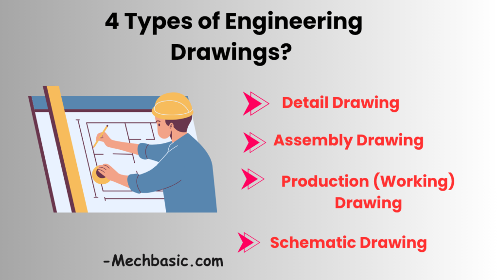
Engineering drawings can be classified in many ways, but the four most important and widely used types are:
- Detail Drawing
- Assembly Drawing
- Production (Working) Drawing
- Schematic Drawing
These drawings serve different purposes during design, manufacturing, assembly, and maintenance.
1. Detail Drawing
Definition
A Detail Drawing shows a single component or part with all the information needed to manufacture it.
It is the most common type of engineering drawing used in workshops and factories.
Purpose
To provide complete information about an individual part.
Information Included
- Dimensions
- Shape
- Material
- Tolerances
- Surface finish
- Manufacturing notes
Example
A shaft drawing may show:
- Diameter = 25 mm
- Length = 150 mm
- Material = Mild Steel
- Surface finish requirements
The machinist can manufacture the shaft using only this drawing.
Applications
Mechanical Engineering
- Shafts
- Gears
- Bearings
- Bolts
Manufacturing
- Individual machine components
Advantages
- Complete manufacturing information
- High accuracy
- Easy inspection
- Supports quality control
Example Components
Gear
Pulley
Shaft
Bolt
Bracket
2. Assembly Drawing
Definition
An Assembly Drawing shows how multiple components fit and work together to form a complete product or machine.
Purpose
To guide assembly operations.
Information Included
- Part locations
- Part numbers
- Assembly sequence
- Relationships between components
Example
A gearbox assembly drawing may show:
Housing
Gears
Shafts
Bearings
Fasteners
all assembled together.
Types of Assembly Drawings
General Assembly Drawing
Shows the complete assembly.
Exploded Assembly Drawing
Shows parts separated for clarity.
Example:
Bolt
↓
Washer
↓
Nut
Installation Assembly Drawing
Shows installation positions.
Applications
Mechanical Engineering
- Engines
- Pumps
- Gearboxes
Manufacturing
- Product assembly
Advantages
- Easy assembly guidance
- Identifies part relationships
- Simplifies maintenance
- Reduces assembly errors
3. Production (Working) Drawing
Definition
A Production Drawing (also called a Working Drawing) contains all the information required to manufacture and inspect a component.
It is often considered an enhanced version of a detail drawing.
Purpose
To provide complete manufacturing instructions.
Information Included
Dimensions
Exact sizes.
Tolerances
Allowed variations.
Example:
25 ± 0.02 mmSurface Finish
Machining quality requirements.
Material Specification
Example:
Mild Steel
Stainless Steel
Cast Iron
Heat Treatment
Example:
Harden and temperWelding Symbols
If required.
Applications
Manufacturing Industry
- CNC machining
- Turning
- Milling
- Grinding
Advantages
- Complete production information
- Supports quality inspection
- Reduces manufacturing mistakes
- Ensures product consistency
4. Schematic Drawing
Definition
A Schematic Drawing uses symbols to represent components and their relationships rather than their actual physical appearance.
Purpose
To explain how a system functions.
Characteristics
- Not drawn to scale
- Uses standard symbols
- Focuses on operation
Examples
Electrical Schematic
Shows:
- Switches
- Motors
- Relays
- Power supply
using symbols.
Hydraulic Schematic
Shows:
- Pumps
- Valves
- Cylinders
Pneumatic Schematic
Shows:
- Compressors
- Air lines
- Direction control valves
Applications
Electrical Engineering
Circuit diagrams.
Mechanical Engineering
Hydraulic systems.
Industrial Automation
PLC control systems.
Advantages
- Easy troubleshooting
- Simplifies complex systems
- Shows system operation clearly
- Universal understanding
Comparison of the Four Types
| Feature | Detail Drawing | Assembly Drawing | Production Drawing | Schematic Drawing |
|---|---|---|---|---|
| Shows Single Part | Yes | No | Usually Yes | No |
| Shows Multiple Parts | No | Yes | Sometimes | Yes (symbolically) |
| Used for Manufacturing | Yes | Limited | Yes | No |
| Used for Assembly | No | Yes | Limited | No |
| Uses Symbols | Limited | Limited | Limited | Extensive |
| Shows Dimensions | Yes | Sometimes | Yes | Usually No |
| Shows Function | Limited | Moderate | Limited | Excellent |
Real-Life Example: Water Pump
A water pump project may require all four drawings:
Detail Drawing
Individual shaft drawing.
Assembly Drawing
Complete pump assembly.
Production Drawing
Manufacturing instructions for impeller.
Schematic Drawing
Electrical motor control circuit.
Other Engineering Drawings
Besides the main four, engineers also use:
Installation Drawing
Shows installation procedures.
Layout Drawing
Shows arrangement of equipment.
Fabrication Drawing
Used for welded structures.
Isometric Drawing
3D representation.
Orthographic Drawing
Multiple 2D views.
Piping Drawing
Industrial piping systems.
Architectural Drawing
Building construction plans.
Importance in Industry
Design Stage
Uses:
- Detail drawings
- Assembly drawings
Manufacturing Stage
Uses:
- Production drawings
Maintenance Stage
Uses:
- Assembly drawings
- Schematic drawings
Inspection Stage
Uses:
- Production drawings
Interview Questions
What are the four main types of engineering drawings?
- Detail Drawing
- Assembly Drawing
- Production (Working) Drawing
- Schematic Drawing
Which drawing is used to manufacture a single component?
Detail Drawing or Production Drawing
Which drawing shows how parts fit together?
Assembly Drawing
Which drawing uses symbols instead of actual shapes?
Schematic Drawing
Which drawing contains tolerances and surface finish requirements?
Production Drawing
Conclusion
The four main types of engineering drawings are Detail Drawings, Assembly Drawings, Production (Working) Drawings, and Schematic Drawings. Detail drawings describe individual parts, assembly drawings show how parts fit together, production drawings provide complete manufacturing instructions, and schematic drawings explain the operation of systems using symbols. Together, these drawings form the foundation of engineering communication in design, manufacturing, assembly, inspection, and maintenance.
Other courses: