
In this article, we discuss various types of lines used in Engineering Drawing.
In this article
- What is a Line?
- Types of lines used in Engineering Drawing?
- Why Should We Use Different Lines in Engineering Drawing?
- Precedence of Lines.
- Conclusion.
What is a Line?
In geometry and engineering drawing, a line is a fundamental element used to represent shapes, dimensions, and boundaries. It is a one-dimensional object that extends infinitely in both directions (in mathematical terms) or is defined with a specific length in practical applications.
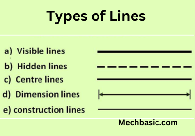
Types of Lines used in Engineering Drawing
The types of lines used in Engineering Drawing is described below:
Here’s a table summarizing the different types of lines used in engineering drawing:
| Line Type | Purpose | Appearance |
|---|---|---|
| Object (Visible) Line | Represents visible edges of an object | Thick, continuous (―) |
| Hidden Line | Shows edges or features not visible in the view | Dashed (_ _ _ _) |
| Center Line | Indicates the center of circles or symmetry | Long-short dashes (— · — · —) |
| Dimension Line | Indicates size (length, width, height) | Thin with arrows (← 50 mm →) |
| Extension Line | Extends from the object to mark dimensions | Thin solid line |
| Leader Line | Connects notes or dimensions to a feature | Thin line with an arrow |
| Section (Cutting Plane) Line | Shows surfaces that have been cut through | Thick dashed or solid line with arrows |
| Hatching (Section) Lines | Used to represent material surfaces in section views | Thin diagonal lines (/////) |
| Break Line | Shortens long objects in drawings | Zigzag or wavy line |
| Phantom Line | Represents alternate positions of parts | Long-short-short dashes (— ·· — ·· —) |
| Border Line | Defines the boundary of the drawing sheet | Thick continuous line |
Why Should We Use Different Lines in Engineering Drawing?
Using different types of lines in engineering drawing is essential for clear communication, accuracy, and standardization. Here’s why:
- Clarity & Readability
- Standardization & Consistency
- Accuracy & Precision
- Differentiation of Features
- Effective Communication
- Saves Time & Cost
Precedence of Lines:
When different types of lines overlap or intersect in a technical drawing, a specific hierarchy is followed to prioritize visibility and importance. This is called the Precedence of Lines. The general rule is:
1. Visible (Object) Lines – Highest Priority
- Always take precedence over other lines.
- Represent the actual shape and edges of the object.
2. Hidden Lines
- Take priority over center lines but are secondary to visible lines.
- Show features that are not directly visible.
3. Cutting Plane Lines
- Used for sectional views, typically override center and phantom lines.
4. Center Lines
- Indicate axes of symmetry, holes, or cylindrical features.
- Take precedence over dimension and extension lines but are secondary to object and hidden lines.
5. Dimension & Extension Lines
- Provide measurements but never interfere with object, hidden, or center lines.
- They should not cross or overlap critical lines unless necessary.
6. Section (Hatching) Lines
- Used to indicate material cut in sectional views.
- Should not dominate the drawing and must remain thin.
7. Phantom Lines – Lowest Priority
- Represent alternate positions of parts or movement paths.
- Do not interfere with more critical lines like object or hidden lines.
Key Rule: More critical features should always be visible, while less important ones should remain in the background.
Conclusion
Lines in engineering drawing are essential for clear, precise, and standardized communication. Each type of line serves a specific purpose, ensuring that drawings are easy to interpret by engineers, manufacturers, and construction professionals. The precedence of lines helps maintain clarity when multiple lines overlap, ensuring that the most important details remain visible.
By following proper line conventions, engineering drawings become a universal language that eliminates confusion, reduces errors, and improves efficiency in design, manufacturing, and construction processes. Mastering these line types is crucial for anyone working in technical fields.
Also Read:
- Lettering Styles and Techniques.
- Principles of Dimensioning.