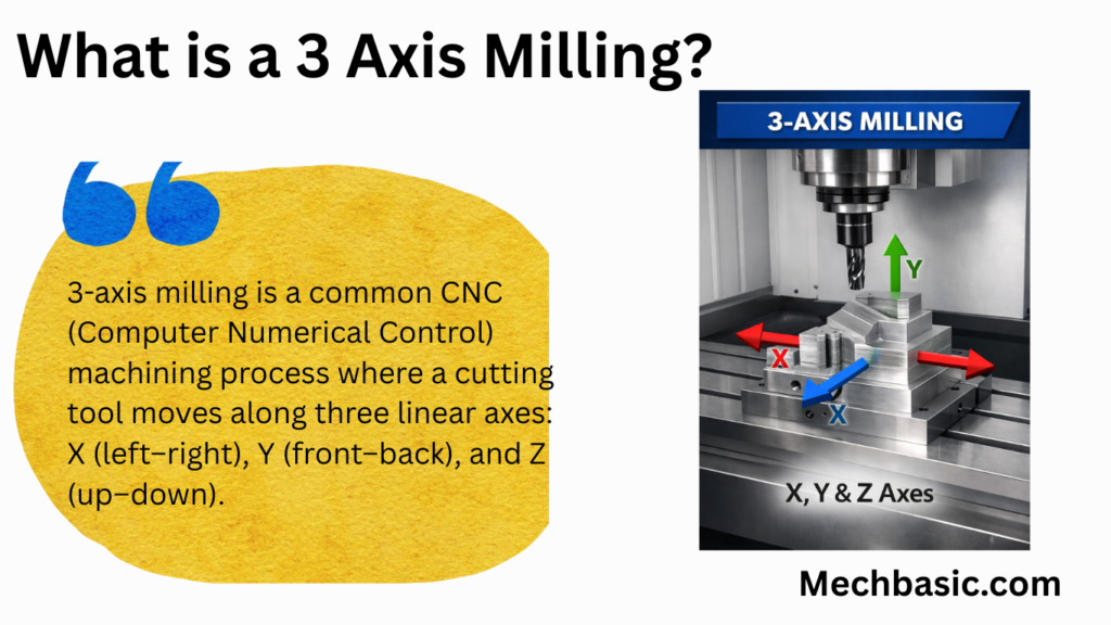
3-axis milling is a common CNC (Computer Numerical Control) machining process where a cutting tool moves along three linear axes: X (left–right), Y (front–back), and Z (up–down). The workpiece remains fixed while the tool removes material to create the desired shape.
In this article:
- 3 Axis Milling:
- 1. What “3 Axes” Means
- 2. How a 3-Axis Milling Machine Works
- 3. Main Components of a 3-Axis Milling Machine
- 4. Common Machining Operations
- 5. Materials Machined on 3-Axis Mills
- 6. Advantages of 3-Axis Milling
- 7. Limitations of 3-Axis Milling
- 8. Typical Applications
- 9. Comparison with Other Milling Types
- 10. When to Use 3-Axis Milling
- Other courses:
3 Axis Milling:
3-axis milling is the most common and fundamental form of CNC (Computer Numerical Control) machining. It uses a rotating cutting tool to remove material from a workpiece while moving along three linear axes.
1. What “3 Axes” Means
In a 3-axis milling machine, the cutting tool or table can move in:
- X-axis – left ↔ right
- Y-axis – front ↔ back
- Z-axis – up ↕ down
👉 The tool cannot tilt or rotate during cutting; it stays perpendicular to the work surface.
2. How a 3-Axis Milling Machine Works
- CAD Model Creation
- The part is designed in CAD software (SolidWorks, Fusion 360, CATIA, etc.).
- CAM Programming
- Toolpaths are generated in CAM software.
- Parameters include:
- Tool type and diameter
- Spindle speed (RPM)
- Feed rate
- Depth of cut
- G-Code Generation
- CAM software converts toolpaths into G-code.
- Example:
G01 X50 Y30 Z-5 F200
- Machining Process
- Workpiece is clamped to the table.
- Tool moves along X, Y, and Z axes to cut the material.
3. Main Components of a 3-Axis Milling Machine
a) Spindle
- Holds and rotates the cutting tool
- Speed typically: 1,000–20,000 RPM
b) Table
- Holds the workpiece
- Moves in X and Y directions (or sometimes the tool moves instead)
c) Linear Guideways & Ball Screws
- Provide precise movement along each axis
d) Controller
- Reads G-code and controls axis motion
e) Tool Holder & Cutting Tools
- End mills, face mills, slot drills, ball nose cutters
4. Common Machining Operations
a) Face Milling
- Produces a flat surface
- Tool moves in X–Y plane
b) Slot Milling
- Creates slots or keyways
c) Pocket Milling
- Removes material inside a closed boundary
d) Contour Milling
- Cuts external or internal profiles
e) Drilling & Boring
- Holes machined along the Z-axis
5. Materials Machined on 3-Axis Mills
- Metals: Aluminum, steel, stainless steel, brass, titanium
- Plastics: ABS, nylon, PEEK
- Composites: Carbon fiber, fiberglass
- Wood & MDF
6. Advantages of 3-Axis Milling
✔ Simple machine design
✔ Lower cost than 4-axis or 5-axis machines
✔ Easy programming and setup
✔ High accuracy for prismatic parts
✔ Widely available and well supported
7. Limitations of 3-Axis Milling
✖ Cannot machine undercuts
✖ Limited access to complex geometries
✖ Multiple setups required for multi-side machining
✖ Longer machining time for complex parts
8. Typical Applications
- Machine brackets
- Engine components
- Molds and dies (simple shapes)
- Jigs and fixtures
- Automotive and aerospace prismatic parts
9. Comparison with Other Milling Types
| Feature | 3-Axis | 4-Axis | 5-Axis |
|---|---|---|---|
| Linear motion | X, Y, Z | X, Y, Z | X, Y, Z |
| Rotary motion | ❌ | 1 axis | 2 axes |
| Complexity | Low | Medium | High |
| Cost | Low | Medium | High |
10. When to Use 3-Axis Milling
Choose 3-axis milling when:
- The part has flat surfaces and simple contours
- No undercuts are required
- Budget and setup time are important
- High production repeatability is needed
Other courses: