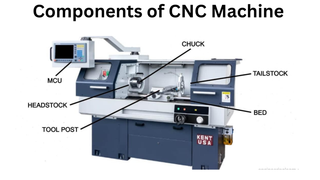
A CNC machine consists of several key components that work together to perform precise machining operations. The seven major parts include the input device, machine control unit (MCU), drive system, machine tool, feedback system, display unit, and power supply.
In this article:
7 Major Parts of a CNC Machine
A CNC (Computer Numerical Control) machine is a sophisticated manufacturing tool that automatically controls machine tools using computer programs. CNC machines can perform milling, turning, drilling, grinding, or cutting operations with high precision.
To understand CNC machines fully, it’s essential to know their major components, which work together to execute programs and produce accurate parts. Below is a detailed description of the 7 major parts of a CNC machine.
1. Machine Frame / Bed
Description
- The structural base of the CNC machine.
- Supports all other components like spindle, axes, and table.
- Provides rigidity and stability during machining.
Functions
- Reduces vibrations during cutting.
- Ensures accuracy and precision.
- Holds linear guides for smooth motion of worktables.
Materials
- Usually made of cast iron, steel, or granite for high stiffness.
2. Control Unit / CNC Controller
Description
- The “brain” of the CNC machine.
- Executes programs written in G-code or M-code.
- Can be open-loop or closed-loop system.
Functions
- Interprets the CNC program.
- Sends commands to motors for axis movement, spindle speed, and tool changes.
- Monitors sensors and feedback to ensure precision.
- Interfaces with the operator via control panel.
Examples
- Fanuc, Siemens, Haas CNC controllers.
3. Spindle / Tool Holder
Description
- The rotating part of the machine that holds the cutting tool (in milling) or rotates the workpiece (in turning).
- In lathes, the spindle rotates the workpiece; in milling, the spindle rotates the tool.
Functions
- Provides rotational motion at desired speed (RPM).
- Transfers torque and power to the cutting tool or workpiece.
- Ensures rigid and precise cutting.
Components
- Motor (direct drive or belt-driven)
- Bearings for smooth rotation
- Tool holder or chuck
4. Axis System (Linear and Rotary Axes)
Description
- CNC machines move the tool or workpiece along controlled axes.
- Axes can be linear (X, Y, Z) or rotary (A, B, C).
Functions
- Enables precise tool positioning.
- Determines machine capability (2-axis, 3-axis, 5-axis, etc.).
- Controls feed motion and cutting path.
Examples
- X-axis: Left-right movement
- Y-axis: Front-back movement
- Z-axis: Up-down movement
- Rotary axes: Tilt or rotation for 5-axis machining
5. Drive System / Motion Mechanism
Description
- System that moves the machine along its axes.
- Can be ball screws, lead screws, or linear motors.
- Powered by servo motors or stepper motors.
Functions
- Converts rotational motion of motors to linear motion of the table or tool.
- Provides high accuracy and repeatability.
- Supports different speeds and feeds.
Components
- Motors (servo/stepper)
- Ball screws or rack-and-pinion
- Linear guides and bearings
6. Work Table / Work Holding Device
Description
- Platform where the workpiece is mounted.
- Can be stationary, moving, or rotary depending on machine type.
- May include vices, clamps, or chucks for holding workpieces.
Functions
- Provides stable support for machining.
- Allows precise positioning of workpiece relative to cutting tool.
- In CNC lathes, the chuck or faceplate rotates the workpiece.
7. Feedback System / Sensors
Description
- Provides real-time information to the controller about position, speed, or load.
- Can be linear encoders, rotary encoders, or limit switches.
Functions
- Ensures high precision and repeatability.
- Detects errors or deviations during machining.
- Enables closed-loop control for CNC accuracy.
Examples
- Position encoders for X, Y, Z axes
- Temperature sensors for spindle
- Tool presence sensors
Summary Table
| Part | Function |
|---|---|
| Machine Frame / Bed | Provides rigidity, reduces vibration, supports other components |
| Control Unit / CNC Controller | Interprets program, controls machine movements |
| Spindle / Tool Holder | Rotates tool or workpiece for cutting |
| Axis System | Controls movement along X, Y, Z (and rotary) axes |
| Drive System / Motion Mechanism | Moves table/tool with motors and screws |
| Work Table / Work Holding Device | Holds workpiece securely and accurately |
| Feedback System / Sensors | Provides real-time position and error information |
Conclusion:
A CNC machine has 7 key parts: a rigid bed, a computer controller, a rotating spindle, axes for movement, a drive system, a table to hold the workpiece, and sensors to ensure accuracy. Together, these parts allow automated, precise, and repeatable machining.
Other courses: