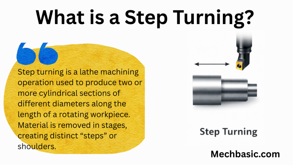
Step turning is a lathe machining operation used to produce two or more cylindrical sections of different diameters along the length of a rotating workpiece. Material is removed in stages, creating distinct “steps” or shoulders.
This operation is commonly used in the manufacturing of shafts, spindles, and mechanical components where precise diameter changes and clear transitions are required. Step turning offers good dimensional accuracy and is a fundamental operation in CNC and conventional turning.
In this article:
- Step Turning (Shoulder Turning)
- 1. Definition
- 2. Purpose of Step Turning
- 3. Principle of Operation
- 4. Types of Step Turning
- 5. Tools Used
- 6. Machine Components Involved
- 7. Cutting Parameters
- 8. Procedure of Step Turning
- 9. Advantages
- 10. Limitations
- 11. Applications
- 12. Safety Precautions
- 13. Difference Between Plain Turning and Step Turning
- 14. Difference Between Step Turning and Taper Turning
Step Turning (Shoulder Turning)
1. Definition
Step turning is a lathe machining operation in which a cylindrical workpiece is turned to different diameters along its length, forming one or more steps (shoulders).
Each step has a uniform diameter, and the transition between two diameters is usually a square or filleted shoulder.
2. Purpose of Step Turning
Step turning is performed to:
- Produce components with multiple diameters
- Create shoulders for assembly and location
- Meet functional and design requirements
- Prepare workpieces for gears, bearings, pulleys, etc.
3. Principle of Operation
- The workpiece rotates about its axis on the lathe.
- A single-point cutting tool is fed parallel to the lathe axis.
- Material is removed in stages to obtain different diameters at specified lengths.
- The tool may also move radially to form sharp shoulders.
4. Types of Step Turning
- Square Shoulder Turning
- Sharp 90° corner between steps
- Used where accurate seating is required
- Chamfered Shoulder Turning
- Chamfer provided at the step
- Prevents stress concentration and damage
- Filleted Shoulder Turning
- Rounded corner between steps
- Improves strength and fatigue life
5. Tools Used
- Single-point turning tool
- HSS tool
- Carbide-tipped tool
- Parting or grooving tool (for precise shoulder formation)
- Chamfering tool (if chamfer is required)
Tool geometry considerations:
- Proper clearance angle
- Suitable nose radius
- Correct rake angle
6. Machine Components Involved
- Headstock
- Chuck / Centers
- Tool post
- Carriage
- Cross-slide (for shoulder formation)
- Tailstock (for long workpieces)
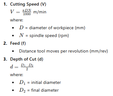
7. Cutting Parameters
8. Procedure of Step Turning
- Study drawing and mark step lengths on the workpiece
- Mount the workpiece securely in the chuck or between centers
- Set the tool at correct center height
- Perform rough turning to remove excess material
- Use longitudinal feed to produce the first step diameter
- Move the tool radially using cross-slide to form the shoulder
- Repeat the operation for remaining steps
- Perform finish turning for accuracy
- Check dimensions using vernier caliper or micrometer
9. Advantages
- Produces complex stepped shafts
- Accurate control over diameter and length
- Essential for functional machine parts
- Can be done on conventional and CNC lathes
10. Limitations
- Time-consuming for multiple steps
- Requires skilled operator for accuracy
- Tool wear affects shoulder precision
11. Applications
- Transmission shafts
- Axles
- Gear shafts
- Bearing seats
- Spindles
- Pulleys and couplings
12. Safety Precautions
- Ensure proper clamping of workpiece
- Keep tool sharp and correctly aligned
- Avoid excessive depth of cut
- Use cutting fluid if required
- Remove chips safely
13. Difference Between Plain Turning and Step Turning
| Plain Turning | Step Turning |
|---|---|
| Uniform diameter throughout | Multiple diameters |
| No shoulders | Shoulders present |
| Simple operation | More complex |
14. Difference Between Step Turning and Taper Turning
| Step Turning | Taper Turning |
|---|---|
| Sudden change in diameter | Gradual change in diameter |
| Cylindrical steps | Conical surface |
| Produces shoulders | No shoulders |
Other courses: