Let’s explore Starter Motors and Alternators in automobiles in complete detail, covering their purpose, construction, working, types, and differences.
These two components are crucial parts of a vehicle’s electrical system — one helps start the engine, and the other generates electricity while it runs.
1. Starter Motor (Starting System)
Purpose:
A starter motor is an electric motor that cranks (rotates) the engine to initiate the combustion process.
Since an internal combustion engine cannot start by itself, the starter motor provides the initial rotation needed to draw in air–fuel mixture and start combustion.
Once the engine starts running, it no longer needs the starter — it runs by its own power.
Main Components of a Starter Motor:
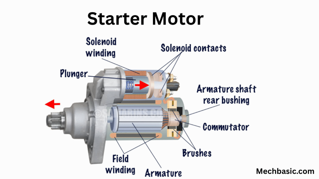
- DC Motor Assembly – Converts electrical energy (from the battery) into mechanical rotation.
- Armature – Rotating coil that cuts magnetic lines of force to produce torque.
- Field Coils or Permanent Magnets – Create magnetic field for armature interaction.
- Commutator and Brushes – Maintain electrical connection between stationary and rotating parts.
- Drive Mechanism (Bendix Drive) – Engages and disengages the starter pinion gear with the engine flywheel.
- Solenoid Switch (Starter Solenoid) – Acts as an electromagnetic relay that connects the battery to the motor when ignition is turned on.
- Pinion Gear – Engages with the flywheel gear ring to crank the engine.
- Flywheel Ring Gear – Fixed to the engine’s crankshaft; the starter drives it to start the engine.
Working Principle of a Starter Motor:
Let’s go step-by-step:
1. Ignition Key Turned to “Start”
- Electrical current from the battery flows to the starter solenoid.
2. Solenoid Activation
- Solenoid creates a magnetic field.
- This pulls a plunger that:
- Pushes the pinion gear forward to mesh with the flywheel.
- Closes a heavy-duty switch that sends current to the starter motor.
3. Motor Cranks Engine
- Electric current flows through armature and field coils → magnetic fields interact → rotational torque is produced.
- The armature shaft rotates the flywheel → engine begins to turn.
4. Engine Starts
- Once the engine starts running, the driver releases the key.
- Solenoid deactivates → pinion gear disengages → starter motor stops.
- The engine now runs under its own power.
Drive Mechanism (Bendix or Inertia Drive)
- Uses a helical gear and spring mechanism.
- When the motor shaft spins, inertia causes the pinion gear to slide along the shaft and engage with the flywheel.
- After engine starts (flywheel spins faster), the pinion automatically disengages to prevent damage.
Electrical Characteristics
- Operates on high current (150–600 A) from a 12V or 24V battery.
- Requires heavy cables to handle large current.
Types of Starter Motors
| Type | Description | Used In |
|---|---|---|
| Direct Drive Starter | Motor shaft directly drives the pinion | Older vehicles |
| Gear Reduction Starter | Uses reduction gears to increase torque | Modern vehicles |
| Permanent Magnet Starter | Uses permanent magnets instead of field coils | Compact cars, motorcycles |
| Coaxial Starter | Solenoid and motor are on same axis | Compact and efficient designs |
Advantages
- Provides high starting torque
- Compact and reliable
- Rapid engine start
- Automatic disengagement
Common Faults
- Weak battery → low cranking speed
- Worn brushes or commutator → no rotation
- Faulty solenoid → starter won’t engage
- Damaged Bendix drive → grinding noise or no engagement
2. Alternator (Charging System)
Purpose:
An alternator is an electrical generator that converts mechanical energy from the engine into electrical energy (AC), which is then rectified to DC to:
- Charge the battery, and
- Power the vehicle’s electrical systems (lights, ignition, radio, sensors, etc.) while the engine runs.
Without an alternator, the car’s electrical system would quickly drain the battery.
Main Components of an Alternator
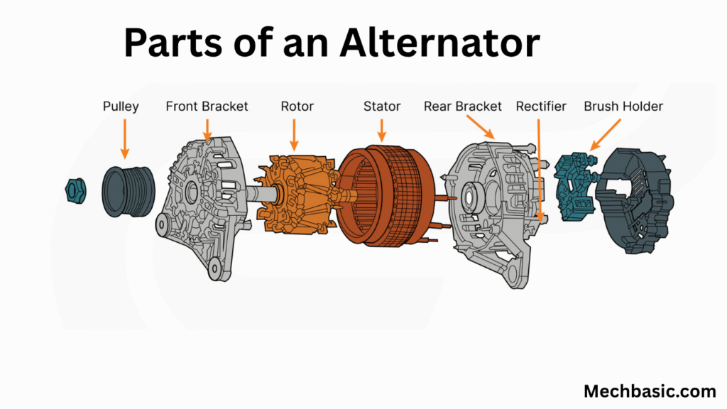
- Rotor (Field Winding) – Rotating electromagnet that produces a magnetic field.
- Stator (Armature) – Stationary set of windings in which AC voltage is induced.
- Slip Rings and Brushes – Supply current to the rotor field winding.
- Rectifier (Diode Bridge) – Converts AC output to DC for battery and electrical systems.
- Voltage Regulator – Controls the field current to maintain constant output voltage (typically ~14 V).
- Pulley and Drive Belt – Connects to the engine crankshaft to drive the alternator.
Working Principle of Alternator
1. Mechanical Drive
- Engine crankshaft drives the alternator pulley via a belt.
2. Magnetic Field Generation
- Battery supplies small current to the rotor winding through brushes and slip rings → creates a rotating magnetic field.
3. Electromagnetic Induction
- As the rotor spins, its magnetic field cuts across the stator windings → alternating voltage (AC) is induced in stator coils.
4. Rectification
- The diode bridge converts this AC voltage to DC voltage suitable for battery charging and powering electronics.
5. Voltage Regulation
- The voltage regulator senses output voltage and adjusts rotor current to keep output steady (e.g., 13.5–14.5 V).
Output Characteristics
| Parameter | Typical Value |
|---|---|
| Output Voltage | 13.5 – 14.5 V DC |
| Output Current | 50 – 200 A (depending on vehicle) |
| Speed Range | Efficient from 1,000 – 6,000 rpm |
Types of Alternators
| Type | Description | Notes |
|---|---|---|
| Conventional Alternator | Belt-driven unit with internal regulator | Most vehicles |
| Brushless Alternator | Uses permanent magnets instead of brushes | Low maintenance |
| Compact Alternator | Small, lightweight, high output | Modern cars |
| Smart Alternator | ECU-controlled; adjusts output for efficiency | Found in hybrid & modern vehicles |
✅ Advantages
- Efficient power generation even at low engine speeds
- Lighter and more reliable than old DC generators
- Automatically charges the battery
- Maintains voltage stability for electronics
⚠️ Common Faults
- Broken drive belt → no charging
- Worn brushes/slip rings → no field current
- Faulty rectifier diodes → low or no output
- Bad voltage regulator → overcharging or undercharging battery
Comparison: Starter Motor vs Alternator
| Feature | Starter Motor | Alternator |
|---|---|---|
| Function | Cranks engine to start it | Generates electricity once engine runs |
| Energy Conversion | Electrical → Mechanical | Mechanical → Electrical |
| Operation Time | Short duration (only at start) | Continuous (while engine runs) |
| Current Type | DC | AC (rectified to DC) |
| Connection | Directly to battery & flywheel | Driven by belt from crankshaft |
| Voltage Regulation | None (full battery voltage) | Controlled by voltage regulator |
| Typical Current Draw | 150–600 A | 50–200 A output |
| Main Components | Armature, field coil, solenoid, pinion gear | Rotor, stator, rectifier, regulator |
| Failure Effect | Engine won’t start | Battery discharges while driving |
Summary
| Aspect | Starter Motor | Alternator |
|---|---|---|
| Purpose | Start engine | Supply electrical power and charge battery |
| Energy Flow | Battery → Starter → Engine | Engine → Alternator → Battery & Loads |
| Type of Machine | DC Motor | AC Generator (with rectifier) |
| Working Duration | Few seconds | Continuous |
| Control | Ignition switch | Voltage regulator / ECU |
| Common Problems | Solenoid or gear issues | Charging or diode failure |
🧠 Key Concept:
- The starter uses battery power to get the engine running.
- The alternator replenishes the battery and supplies electrical energy once the engine is running.
Would you like me to include labeled diagrams of both the starter motor and alternator (with internal parts and current flow)?
Other courses: