
Reading an HVAC wiring diagram involves understanding symbols, wire colors, and circuit functions. Here’s a step-by-step guide:

What is an HVAC Wiring Diagram?
An HVAC wiring diagram is a schematic representation of the electrical connections and components in a heating, ventilation, and air conditioning system. It shows how wires, relays, switches, and controls are interconnected for proper operation.
How to Read HVAC Wiring Diagram?
Step1:
Understand the Types of HVAC Wiring Diagrams:
- Schematic Diagram: Shows the electrical circuit using symbols. Used for troubleshooting.

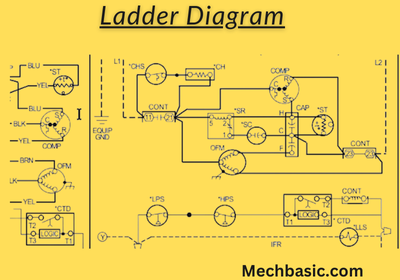
- Ladder Diagram: Represents circuits in a vertical layout like a ladder.
- Pictorial Diagram: Shows actual component locations with wiring.
Step 2:
Identify Key Components:
- Power Source: Usually labeled L1 (hot) and L2 (neutral) for AC voltage.
- Transformer: Steps down voltage (often 120V/240V to 24V for controls).
- Thermostat: Controls heating and cooling.
- Relays & Contactors: Control high-power devices like compressors and fans.
- Capacitors: Store energy for motors.
- Blower Motor, Compressor, & Condenser Fan: Essential components for HVAC function.
Step 3:
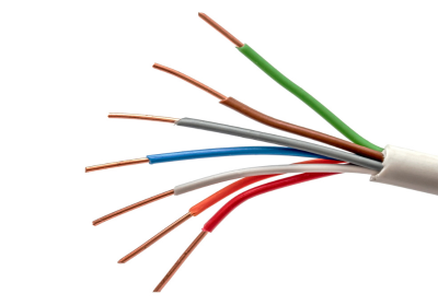
Learn Common Wire Colors:
- R (Red) – 24V power from the transformer.
- C (Blue or Black) – Common (ground) return path for 24V.
- Y (Yellow) – Cooling signal to compressor.
- W (White) – Heating signal to furnace or heat strip.
- G (Green) – Controls blower fan.
- O/B (Orange or Blue) – Reversing valve in heat pumps.
Step 4:
Follow the Wiring Paths:
- Trace wires from power source → thermostat → relays/contactors → load (compressor, blower, etc.).
- Identify control circuits vs. power circuits.
- Look for connections to safety switches (limit switches, pressure switches, etc.).
Step 5:
Recognize Symbols:
- Lines – Wires connecting components.
- Dots – Indicate a connection.
- Switches – Represent on/off mechanisms (thermostat contacts, safety switches).
- Coils & Contacts – Show relay and contactor operations.
- Ground & Neutral – Essential for circuit completion.
For more wiring symbols ,
Read: All Electrical wiring symbols.
Step 6:
Check for Safety Features:
- Fuses & Circuit Breakers: Protect the system.
- Limit Switches: Prevent overheating.
- Pressure Switches: Ensure safe refrigerant pressure.
Step 7:
Compare with the Actual System:
- Use a multimeter to check voltage and continuity if troubleshooting.
- Ensure wiring matches the diagram before powering on.
Read More: HVAC Wiring and schematics.
Other Courses:


