Plain turning, also known as straight turning, is a basic lathe operation in which a cutting tool moves parallel to the axis of a rotating workpiece to reduce its diameter and produce a smooth, cylindrical surface.
It is commonly used to achieve accurate diameters, uniform surfaces, and proper dimensional control in shafts and round components. Plain turning is one of the most fundamental and widely used operations in CNC and conventional turning.
In this article:
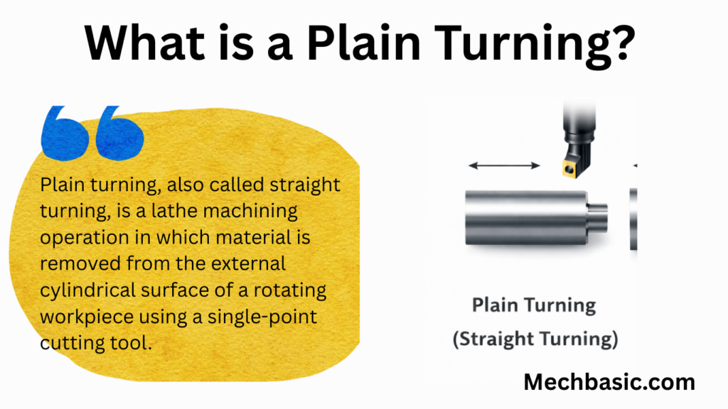
Plain Turning (Straight Turning)
1. Definition
Plain turning, also called straight turning, is a lathe machining operation in which material is removed from the external cylindrical surface of a rotating workpiece using a single-point cutting tool.
The tool moves parallel to the axis of rotation, producing a uniform diameter along the length of the workpiece.
2. Purpose of Plain Turning
Plain turning is carried out to:
- Reduce the diameter of a workpiece
- Produce accurate cylindrical surfaces
- Improve dimensional accuracy
- Obtain a smooth surface finish
- Prepare the workpiece for further operations (threading, knurling, taper turning, etc.)
3. Principle of Operation
- The workpiece is mounted in the chuck or between centers and rotated by the spindle.
- A single-point cutting tool is fed longitudinally (parallel to the lathe axis).
- The cutting edge removes excess material in the form of chips.
- The final diameter depends on depth of cut and number of passes.
4. Types of Plain Turning
- Rough Turning
- Removes large amounts of material
- High depth of cut and feed rate
- Surface finish is relatively rough
- Used for initial size reduction
- Finish Turning
- Removes small amounts of material
- Low feed and shallow depth of cut
- Produces accurate dimensions and smooth surface
5. Tools Used
- Single-point turning tool
- High Speed Steel (HSS)
- Carbide tipped tool
- Ceramic or coated carbide (for high-speed operations)
Tool geometry includes:
- Rake angle
- Clearance angle
- Nose radius (affects surface finish)
6. Machine Components Involved
- Headstock – rotates the workpiece
- Chuck / Centers – holds the workpiece
- Tool post – holds the cutting tool
- Carriage – provides longitudinal feed
- Lead screw / Feed rod – controls tool movement
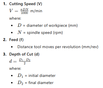
7. Cutting Parameters
8. Procedure of Plain Turning
- Select appropriate cutting tool and parameters
- Mount the workpiece securely in the chuck or between centers
- Set the cutting tool at correct height (center height)
- Start the lathe at suitable speed
- Engage longitudinal feed
- Perform rough turning if required
- Perform finish turning for accuracy and surface finish
- Measure the diameter using vernier caliper or micrometer
9. Advantages
- Simple and widely used operation
- High dimensional accuracy achievable
- Suitable for mass and batch production
- Can be automated using CNC lathes
10. Limitations
- Limited to cylindrical shapes
- Tool wear affects accuracy
- Requires proper tool setup and alignment
11. Applications
- Shafts
- Rods
- Pins
- Bushes
- Spindles
- Machine components requiring cylindrical geometry
12. Safety Precautions
- Wear safety goggles
- Ensure workpiece is tightly clamped
- Remove chuck key before starting
- Avoid loose clothing
- Use proper cutting speed and feed
13. Difference Between Plain Turning and Facing
| Plain Turning | Facing |
|---|---|
| Tool moves parallel to axis | Tool moves perpendicular to axis |
| Produces cylindrical surface | Produces flat surface |
| Reduces diameter | Reduces length |
Other courses: