Lathe tool geometry refers to the shape and angles of a cutting tool used in turning operations, which directly affect cutting efficiency and surface finish.
Key angles include rake angle, clearance angle, and cutting edge angle, each influencing chip flow and tool life.
Proper tool geometry helps reduce cutting forces, improve accuracy, and extend the tool’s lifespan.
In this article:
Lathe tool geometry
Lathe tool geometry is all about how the cutting tool is shaped and oriented so it cuts material efficiently, produces a good surface finish, and lasts longer. Let’s break it down clearly and in detail.
1. Main Parts of a Lathe Tool
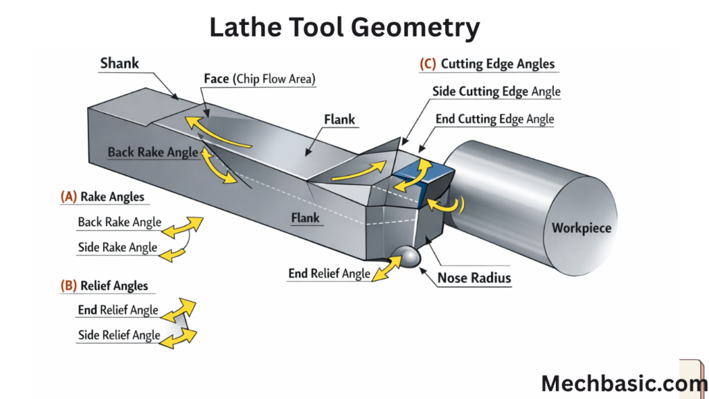
A single-point cutting tool (used on a lathe) has:
- Shank → the body held in the tool post
- Face → surface over which chips flow
- Flank → surface facing the workpiece
- Cutting edge → edge that removes material
- Nose → tip where edges meet
2. Important Angles in Tool Geometry
These angles control cutting performance:
(A) Rake Angles
These affect chip flow and cutting force.
1. Back Rake Angle
- Slope of tool face from tip toward shank (backward direction)
- Function:
- Helps chip flow backward
- Reduces cutting force
- Positive rake: easier cutting, weaker tool
- Negative rake: stronger tool, more force required
2. Side Rake Angle
- Slope sideways from cutting edge
- Function:
- Directs chip sideways
- Reduces cutting resistance
(B) Relief (Clearance) Angles
Prevent rubbing between tool and workpiece.
3. End Relief Angle
- Clearance below the cutting edge (front)
- Prevents tool from rubbing on work surface
4. Side Relief Angle
- Clearance on the side of the tool
- Avoids friction with machined surface
(C) Cutting Edge Angles
5. Side Cutting Edge Angle (Lead Angle)
- Angle between side cutting edge and workpiece axis
- Function:
- Spreads cutting load over longer edge
- Improves tool life
6. End Cutting Edge Angle
- Angle between end cutting edge and work surface
- Prevents tool digging into workpiece
(D) Nose Radius
- Rounded tip of tool
Effects:
- Larger radius → better surface finish, more strength
- Smaller radius → sharper cutting, less vibration control
3. Tool Signature (ASA System)
Lathe tool geometry is often written as a sequence of angles:
Example:
Back rake – Side rake – End relief – Side relief – End cutting edge – Side cutting edge – Nose radius
👉 Example:
8° – 10° – 6° – 6° – 8° – 15° – 0.8 mm
4. Functions of Tool Geometry
✔️ Controls Cutting Forces
- Positive rake → lower force
- Negative rake → higher strength
✔️ Influences Chip Formation
- Proper rake ensures smooth chip flow
✔️ Affects Surface Finish
- Nose radius and angles determine smoothness
✔️ Tool Life
- Correct angles reduce wear and heat
5. Typical Angle Selection (General Guidelines)
| Material | Rake Angle | Relief Angle | Nose Radius |
|---|---|---|---|
| Soft materials (Aluminum) | High positive | Moderate | Large |
| Medium (Steel) | Moderate | Moderate | Medium |
| Hard materials (Cast iron) | Low/negative | Small | Small |
6. Common Mistakes in Tool Geometry
- Too little relief → rubbing, heat
- Too much rake → weak tool edge
- Small nose radius → rough finish
- Wrong cutting edge angle → chatter
Summary
- Rake angles → chip flow & cutting ease
- Relief angles → prevent rubbing
- Cutting edge angles → direction & load
- Nose radius → finish & strength
Other courses: