
In this article, we discuss how to design Propeller in Solid works.(Step by step Approach)

How to Design a Propeller in SolidWorks:
Designing a propeller in SolidWorks involves creating airfoil blades, adding twist, and ensuring aerodynamic efficiency. Follow these steps:
Step 1: Create a New Part
- Open SolidWorks → Click New → Select Part.
- Go to Front Plane → Click Sketch.
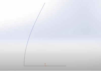
Step 2: Draw the Propeller Profile
- Use Spline or Arc Tool to create the airfoil shape of one blade.
- Define dimensions using Smart Dimension.
- Use Fillet or Chamfer to smooth sharp edges.
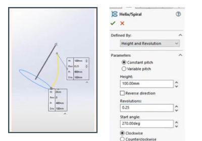
Step 3: Create the Blade Curve (Twist Effect)
- Go to Right Plane → Create a new sketch.
- Draw a helix or spiral curve to represent the blade twist.
- Adjust pitch and turns as per aerodynamics requirements.
Step 4: Loft the Blade Shape
- Select Loft Boss/Base under Features tab.
- Select the airfoil sketches and twist curve as guide.
- Click OK to generate the 3D blade.
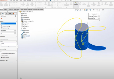
Step 5: Create the Propeller Hub
- Select Front Plane → Create a circular sketch for the hub.
- Use Extrude Boss/Base to give thickness.
- Add a center hole for the shaft using Extruded Cut.
Step 6: Duplicate Blades Using Circular Pattern
- Click Circular Pattern in the Features tab.
- Select the blade as the feature to copy.
- Select the center axis and specify the number of blades (e.g., 2, 3, or 4).
- Click OK to finalize.
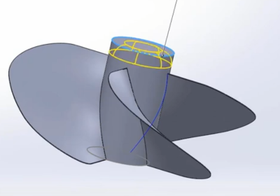
Step 7: Apply Fillets & Finishing Touches
- Use Fillet Tool to round edges for a smooth aerodynamic look.
- Add Material (Aluminum, Plastic, etc.) using Appearance Manager.
- Use Render Tool for realistic visualization.
Step 8: Save & Export
- Save as SolidWorks Part (.SLDPRT).
- Export as STL if needed for 3D printing or simulation.
Optional: Run Flow Simulation
- Go to SolidWorks Flow Simulation.
- Set air velocity, direction, and density.
- Run the simulation to test aerodynamics and efficiency.
🚀 Your propeller is now designed!