Today’s vehicles don’t just have “dumb” alternators that always charge at a fixed voltage — instead, they use ECU-controlled alternators (also called smart alternators or computer-controlled charging systems).
Let’s go through this in complete detail — from how traditional alternators worked, to how ECU-controlled ones differ, what components are involved, and what benefits and challenges come with them.
1. Traditional (Old-Style) Alternator
In older vehicles (pre-2000s):
- The alternator had a built-in voltage regulator.
- Its job was simple: keep the battery voltage steady at ~14.4 V.
- It continuously charged the battery regardless of conditions.
That meant:
✅ Simple design
❌ Inefficient — wasted fuel and energy
❌ Didn’t adapt to vehicle load or driving conditions
2. ECU-Controlled (Smart) Alternator
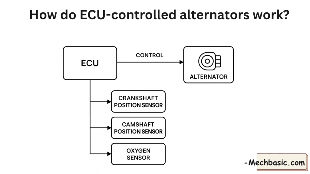
An ECU-controlled alternator is part of a smart charging system where the Engine Control Unit (ECU) — or a separate Charging Control Module — actively controls how much the alternator charges and when.
Instead of always maintaining a fixed 14V output, the ECU varies the alternator’s output voltage and current based on:
- Engine load
- Battery state of charge (SOC)
- Temperature
- Vehicle speed
- Electrical demand
- Regenerative braking status (on hybrids/start-stop systems)
3. Basic Principle of Operation
In Simple Terms:
The ECU monitors electrical system conditions and commands the alternator to adjust its output using a field control signal.
The Components Involved
| Component | Function |
|---|---|
| Alternator | Generates electrical energy from engine rotation |
| Field Coil (Rotor) | Magnetic field strength controls alternator output |
| Voltage Regulator (smart or internal) | Responds to ECU signal to control field current |
| ECU / PCM (Powertrain Control Module) | Calculates desired charging voltage based on inputs |
| Battery Current Sensor | Measures current going in/out of the battery |
| Battery Temperature Sensor | Compensates voltage based on temperature |
| Communication Line (LIN, PWM, or BSS) | Carries control signals between ECU and alternator |
4. How the ECU Controls the Alternator (Step by Step)
Let’s break it down:
Step 1: ECU Monitors Electrical System
The ECU constantly monitors:
- Battery voltage
- Battery current (via current sensor)
- Battery temperature
- Engine load & RPM
- Electrical accessories (A/C, lights, defogger, etc.)
Step 2: ECU Calculates Desired Output
Based on all those readings, the ECU decides how much voltage the alternator should produce.
For example:
| Situation | ECU Command |
|---|---|
| Battery low | Raise voltage to ~14.8V for fast charging |
| Battery full | Lower voltage to ~12.6V to reduce load |
| Heavy electrical load (A/C, lights on) | Maintain ~14V |
| Acceleration | Temporarily reduce alternator output to free engine power |
| Deceleration / braking | Increase alternator output to charge battery efficiently |
Step 3: ECU Sends Control Signal to Alternator
The ECU sends a control signal to the alternator using one of the following methods:
| Control Type | Signal Type | Description |
|---|---|---|
| LIN Bus (Local Interconnect Network) | Digital serial communication | Common in modern cars (post-2010) |
| PWM (Pulse Width Modulation) | Duty-cycle signal (5V square wave) | Used in many 2000s-era vehicles |
| BSS / PCM Field Control | Analog voltage | Older ECU-controlled systems |
The alternator’s internal regulator adjusts the field current to match the requested output voltage.
Step 4: Alternator Adjusts Its Output
By increasing or decreasing field coil current, the alternator adjusts:
- Its magnetic field strength, and
- Therefore, the charging voltage and current output.
This allows precise control of charging behavior.
Step 5: ECU Monitors Feedback
Most systems include a feedback line or use the LIN network to confirm the alternator’s actual output.
If it doesn’t match the command → ECU sets a diagnostic trouble code (DTC) such as:
- P0622 — Generator Field Control Circuit
- P0621 — Generator Lamp “L” Control Circuit
- U1xxx — LIN Bus Communication Error with Generator
5. Why Automakers Use ECU-Controlled Alternators
1. Fuel Efficiency (Reduced Engine Load)
- Alternator creates mechanical drag on the engine.
- By lowering output during acceleration, the ECU reduces that drag → better MPG.
2. Optimized Charging
- Prevents overcharging or undercharging.
- Adapts to temperature, state of charge, and driving conditions.
3. Regenerative Charging
- On deceleration or braking, ECU increases alternator load.
- Converts kinetic energy into electrical energy (similar to mild regenerative braking).
4. Better Battery Life
- Maintains ideal charging voltage profile.
- Prevents overheating or overcharging the battery.
5. Reduced Emissions
- Less alternator load → less fuel burned → lower CO₂ emissions.
6. Common Problems in ECU-Controlled Alternator Systems
| Problem | Cause | Symptom |
|---|---|---|
| LIN or PWM communication fault | Broken wire or module error | Battery light ON, low charge |
| Battery current sensor fault | Open circuit or bad connection | Incorrect charging behavior |
| ECU software glitch | Outdated firmware | Intermittent over/undercharging |
| Corroded ground or power connections | High resistance | Fluctuating voltage |
| Faulty alternator regulator | Internal failure | No response to ECU command |
| Aftermarket alternator (non-compatible) | Wrong type (non-LIN) | No communication, warning light |
7. Diagnosing ECU-Controlled Alternator Problems
Step 1️⃣ — Check Battery Voltage
- Key off: 12.6V
- Engine idling: 13.5–14.8V (varies by load)
- If voltage is below 13V and doesn’t change → alternator may not be receiving control signal.
Step 2️⃣ — Scan for DTCs
Use a scan tool capable of reading ECU and charging system modules.
Look for:
- P0622, P0621, P0560, Uxxxx codes.
Step 3️⃣ — Check LIN or PWM Signal
Use an oscilloscope or graphing multimeter:
- PWM should show a 5V square wave, duty cycle varying from 10%–90%.
- LIN should show digital serial data pulses at 12V levels.
If signal missing → wiring, connector, or ECU issue.
Step 4️⃣ — Verify Alternator Communication
Some diagnostic scanners show “Generator Communication = OK” or “Generator Command Voltage” — confirming the alternator and ECU are talking.
8. Typical Voltage Variation (Example)
| Condition | Alternator Command Voltage |
|---|---|
| Idle, low load | 13.2 V |
| Engine cranking recovery | 14.8 V |
| Acceleration | 12.5 V (to reduce drag) |
| Deceleration | 14.8–15.2 V (charge boost) |
| Battery hot | Lowered voltage (~13.5 V) |
| Battery cold | Higher voltage (~14.9 V) |
9. Example — How It Works in Real Time
Imagine driving on a highway:
- Cruising steady → alternator output ~13.2 V
(battery fully charged, minimal load) - Accelerate to overtake → ECU momentarily reduces alternator field current → less drag → more engine power
- Release throttle → ECU increases alternator output to 14.8 V → recharges battery efficiently
- Stop at light → alternator drops output to save fuel if battery is healthy
This continuous voltage modulation happens several times per second.
10. Summary — ECU-Controlled Alternator
| Feature | Traditional Alternator | ECU-Controlled Alternator |
|---|---|---|
| Control | Internal regulator only | ECU commands voltage |
| Output voltage | Fixed (~14.4V) | Variable (12–15V) |
| Communication | None | LIN, PWM, or analog signal |
| Fuel efficiency | Average | Improved |
| Battery management | Basic | Intelligent (temp & SOC-based) |
| Regenerative capability | No | Yes (during decel/braking) |
| Diagnostic ability | Limited | Extensive via OBD-II |
| Compatibility | Simple replacement | Must match ECU protocol |
Pro Tip
If you replace an ECU-controlled alternator:
- Always match the part number or communication type (LIN/PWM/etc.)
- After installation, perform charging system initialization or battery registration (especially on BMW, Ford, VW, Hyundai, etc.)
- Using a non-ECU alternator in a smart-charging vehicle will cause low charging voltage and warning lights.
Other courses: