Chamfer turning is a lathe machining operation used to create a beveled (angled) edge at the end of a cylindrical workpiece. The chamfer is typically cut at a standard angle, such as 45°, to remove sharp edges, improve safety, enhance appearance, and aid in assembly.
This operation is commonly performed after facing or straight turning and is widely used in mechanical and manufacturing industries to ensure proper fit and finish of components.
In this article:
- Chamfer Turning (Chamfering) in Lathe Machining
- 1. What is Chamfer Turning?
- 2. Purpose of Chamfer Turning
- 3. Principle of Chamfer Turning
- 4. Tools Used for Chamfer Turning
- 5. Chamfer Turning Setup
- 6. Methods of Chamfer Turning
- 7. Steps in Chamfer Turning (Manual Lathe)
- 8. Chamfer Specifications
- 9. Cutting Parameters (Typical)
- 10. Common Defects & Remedies
- 11. Advantages
- 12. Applications
- 13. Difference Between Chamfering and Filleting
Chamfer Turning (Chamfering) in Lathe Machining
1. What is Chamfer Turning?
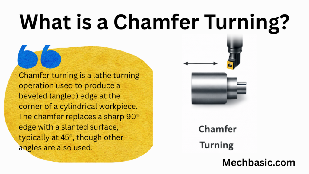
Chamfer turning is a lathe turning operation used to produce a beveled (angled) edge at the corner of a cylindrical workpiece.
The chamfer replaces a sharp 90° edge with a slanted surface, typically at 45°, though other angles are also used.
2. Purpose of Chamfer Turning
- To remove sharp edges
- To prevent injury during handling
- To facilitate assembly (easy insertion into holes)
- To protect edges from chipping
- To improve appearance and finish
- To prepare edges for threading or welding
3. Principle of Chamfer Turning
- The workpiece rotates in the spindle.
- The cutting tool is fed at an inclined angle to the axis of the workpiece.
- Material is removed from the corner to form a sloped surface.
4. Tools Used for Chamfer Turning
- Single-Point Chamfer Tool
- Ground to required chamfer angle (commonly 45°)
- HSS or carbide
- Combination Tool
- Turning + chamfering edge
- Form Tool
- For mass production and CNC operations
Tool materials:
- HSS
- Carbide tipped tools
- Indexable carbide inserts (CNC)
5. Chamfer Turning Setup
- Work holding: 3-jaw chuck, 4-jaw chuck, or collet
- Tool setting:
- Tool tip at center height
- Tool angle set equal to chamfer angle
- Compound rest method (manual lathe):
- Compound slide set at 45° (or required angle)
6. Methods of Chamfer Turning
a) By Compound Slide
- Compound slide is swiveled to chamfer angle
- Tool is fed manually along the compound slide
- Most accurate method
b) By Form Tool
- Tool shape matches chamfer profile
- Used for repetitive production
c) By CNC Programming
- Tool moves along a programmed angled path
- High accuracy and repeatability
7. Steps in Chamfer Turning (Manual Lathe)
- Secure workpiece in the chuck.
- Face the end of the workpiece (if required).
- Set chamfer tool at center height.
- Swivel compound slide to desired angle (e.g., 45°).
- Start the lathe at suitable speed.
- Feed the tool gradually to remove material.
- Measure chamfer size.
- Retract tool and stop the machine.
8. Chamfer Specifications
Chamfers are commonly specified as:
- Angle × Length →
45° × 2 mm - Two equal sides →
2 × 2 mm chamfer - C dimension →
C2(means 2 mm at 45°)
9. Cutting Parameters (Typical)
- Speed: Slightly lower than straight turning
- Feed: 0.05–0.2 mm/rev
- Depth of cut: Depends on chamfer size
- Coolant: Recommended for better finish and tool life
10. Common Defects & Remedies
| Defect | Cause | Remedy |
|---|---|---|
| Uneven chamfer | Tool angle incorrect | Reset compound angle |
| Rough surface | Blunt tool, low speed | Sharpen tool, increase speed |
| Overcut chamfer | Excess feed | Reduce feed, check measurement |
| Burr formation | Low speed | Use finishing pass |
11. Advantages
- Improves safety and appearance
- Enhances assembly performance
- Reduces stress concentration
- Simple and economical operation
12. Applications
- Shafts and pins
- Bolts and screws
- Bushings
- Automotive and machine components
13. Difference Between Chamfering and Filleting
| Chamfer | Fillet |
|---|---|
| Straight angled edge | Rounded edge |
| Easy to machine | Requires radius tool |
| Used for assembly | Used to reduce stress |
Other courses: