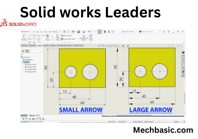
To adjust the leader length in SOLIDWORKS (such as for dimensions, notes, or annotations), follow these steps:
Method 1: Dragging the Leader
- Select the dimension or note with the leader.
- Hover over the leader line until the pointer changes to a move or drag symbol.
- Click and drag the leader endpoint to adjust its length manually.
Method 2: Using the Dimension Property Manager
- Select the dimension or note with the leader.
- In the Property Manager, locate the section related to leaders (e.g., “Leaders” or “Leader Display”).
- Modify the Leader Style or associated parameters, like alignment or break points, to adjust its position or length.
Method 3: Adjusting with Settings
- Go to Tools > Options > Document Properties > Dimensions.
- Under the Leader/Arrow settings, you can adjust defaults for leader display, such as offset distances or styles.
Also Read:
Still not cleared, check out the video below for more details:
Tips for Fine-Tuning:
- Use dynamic drag handles for precise adjustments on-the-fly.
- Ensure proper alignment by enabling snap-to-grid or using relations like horizontal or vertical alignment for leader endpoints.
- If multiple leaders need adjustment, select them all and edit their properties simultaneously.
These methods ensure the leader length suits your design and maintains clarity in annotations.
