
In this article, we discuss the various types of Engineering Drawings in detail.
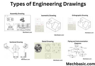
Types of Drawings in Engineering
In engineering, several types of drawings are used to communicate design, construction, and operational details. The main types include:
- Orthographic Drawings.
- Isometric Drawings.
- Assembly Drawings.
- Sectional Drawings.
- Detail Drawings.
- Schematic Drawings.
- Piping and Instrumentation Diagrams (P&ID).
- Construction Drawings.
- Flowcharts and Diagrams.
Here the some basic explanations about these drawings.
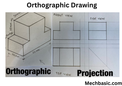
Orthographic Drawings:
These show a 2D representation of an object from multiple views (top, front, side) to provide accurate dimensions and details.
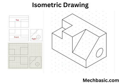
Isometric Drawings:
These are 3D representations of objects, drawn at an angle to show all three dimensions (height, width, depth) in one view.
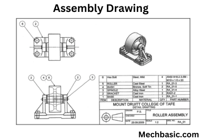
Assembly Drawings:
These show how different parts of a product fit together, often with exploded views to clarify the assembly process.
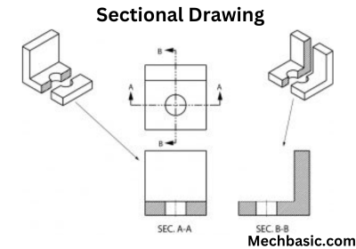
Sectional Drawings:
These illustrate a cut-through view of an object to show internal features, providing a better understanding of complex designs.
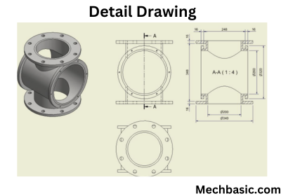
Detail Drawings:
These zoom in on specific parts or features of a design to provide more precise dimensions and information.
Schematic Drawings:
Commonly used in electrical engineering, these diagrams represent the components of a system and their connections in a simplified form.
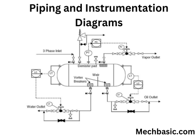
Piping and Instrumentation Diagrams (P&ID):
These are used in process engineering to show the layout of piping systems and the relationships between mechanical components and instrumentation.
Construction Drawings:
These detail the specifications, dimensions, and materials used in constructing buildings, bridges, or other infrastructure projects.
Flowcharts and Diagrams:
Used to represent processes or systems, often in mechanical or industrial engineering, to visualize workflows or production steps.
Each type of drawing serves a unique purpose, depending on the stage of the design process and the level of detail required.