
CNC machining uses computer-controlled machines to manufacture parts with high accuracy and precision.
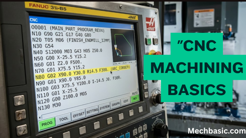
G-code is the programming language that controls machine movements, cutting operations, and tool paths.
Learning basic G-code commands helps in operating CNC machines and producing accurate components.
In this article:
- CNC Machining Basics: A Guide to G-code
- What is CNC Machining?
- How CNC Machining Works
- Advantages of CNC Machining
- Components of a CNC Machine
- What is G-code?
- Structure of a G-code Program
- Common G-code Commands
- Common M-code Commands
- Other Common Program Words
- Example of a Simple G-code Program
- Coordinate Systems
- Feed Rate and Spindle Speed
- Safety Guidelines for CNC Machining
- Applications of CNC Machining
- Advantages of Learning G-code
- Common Mistakes Beginners Make
- Tips for Beginners
- Summary Table
- Frequently Asked Questions (FAQs)
- Conclusion
CNC Machining Basics: A Guide to G-code
Introduction
Computer Numerical Control (CNC) machining is one of the most important manufacturing technologies in modern engineering. It uses computer-controlled machine tools to produce highly accurate and repeatable parts from materials such as metals, plastics, wood, and composites. CNC machining is widely used in industries including automotive, aerospace, medical, electronics, defense, energy, and industrial manufacturing.
At the heart of CNC machining is G-code, a standardized programming language that instructs CNC machines how to move, cut, drill, and shape materials. Understanding G-code is a fundamental skill for CNC operators, machinists, manufacturing engineers, and mechanical engineering students.
This guide explains the basics of CNC machining, introduces G-code programming, and provides practical examples to help beginners understand how CNC machines operate.
What is CNC Machining?
Definition
CNC (Computer Numerical Control) machining is a manufacturing process in which pre-programmed computer software controls the movement of machine tools such as mills, lathes, routers, grinders, and laser cutters.
Instead of being operated manually, CNC machines execute programmed instructions to manufacture parts with high precision and consistency.
How CNC Machining Works
The CNC machining process typically follows these steps:
- Create a 3D model using CAD software.
- Convert the CAD model into toolpaths using CAM software.
- Generate G-code from the CAM software.
- Transfer the G-code program to the CNC machine.
- Secure the workpiece and cutting tools.
- Set machine coordinates and tool offsets.
- Run the program to machine the part.
- Inspect the finished component for accuracy and quality.
Advantages of CNC Machining
CNC machining offers several benefits:
- High precision and repeatability.
- Increased production speed.
- Reduced human error.
- Ability to produce complex geometries.
- Improved surface finish.
- Consistent product quality.
- Lower labor costs for high-volume production.
- Easy modification of programs for design changes.
Components of a CNC Machine
1. Machine Control Unit (MCU)
The MCU is the computer that interprets G-code and controls machine movements.
Functions
- Reads G-code commands.
- Controls axis movement.
- Regulates spindle speed.
- Coordinates tool changes.
2. Machine Bed
Provides a rigid foundation for the machine, minimizing vibration and ensuring machining accuracy.
3. Spindle
The spindle rotates the cutting tool (or the workpiece in a lathe).
Important parameters include:
- Speed (RPM)
- Direction of rotation
- Power
4. Axes
CNC machines move along different axes.
- X-axis: Left–Right movement
- Y-axis: Front–Back movement
- Z-axis: Up–Down movement
Advanced machines may also include:
- A-axis (rotation around X)
- B-axis (rotation around Y)
- C-axis (rotation around Z)
5. Cutting Tools
Common cutting tools include:
- End mills
- Drill bits
- Face mills
- Ball nose cutters
- Reamers
- Taps
6. Tool Changer
Automatically changes cutting tools during machining to improve efficiency.
What is G-code?
Definition
G-code is the standard programming language used to control CNC machine movements and machining operations.
The letter “G” stands for Geometric or Preparatory functions.
G-code commands specify:
- Tool movement
- Position
- Feed rate
- Spindle speed
- Cutting operations
- Coordinate systems
Structure of a G-code Program
A typical G-code program consists of numbered lines (blocks), each containing one or more commands.
Example:
N10 G21
N20 G90
N30 G00 X0 Y0
N40 M03 S1200
N50 G01 X50 Y0 F200
N60 G01 X50 Y50
N70 M05
N80 M30
Each line performs a specific operation in sequence.
Common G-code Commands
G00 – Rapid Positioning
Moves the tool quickly to a specified location without cutting.
Example:
G00 X20 Y30G01 – Linear Interpolation
Moves the tool in a straight line at the specified feed rate while cutting.
Example:
G01 X100 Y50 F250G02 – Clockwise Circular Interpolation
Creates a clockwise arc.
Example:
G02 X50 Y50 I10 J0G03 – Counterclockwise Circular Interpolation
Creates a counterclockwise arc.
Example:
G03 X0 Y50 I-25 J0G17, G18, G19 – Plane Selection
- G17 – XY plane
- G18 – XZ plane
- G19 – YZ plane
G20 and G21 – Units
- G20 – Inches
- G21 – Millimeters
G28 – Return to Home Position
Moves the machine to its reference (home) position.
G40 – Cancel Cutter Radius Compensation
Cancels any active cutter compensation.
G41 and G42 – Cutter Compensation
- G41 – Left compensation
- G42 – Right compensation
G54 to G59 – Work Coordinate Systems
Define different work offsets for multiple setups or fixtures.
G90 – Absolute Programming
Coordinates are measured from the workpiece origin.
Example:
G90
X100 Y50
G91 – Incremental Programming
Coordinates are measured from the current tool position.
Example:
G91
X20 Y10
Common M-code Commands
M-codes control machine functions rather than movement.
| M-code | Function |
|---|---|
| M00 | Program stop |
| M01 | Optional stop |
| M03 | Spindle clockwise |
| M04 | Spindle counterclockwise |
| M05 | Stop spindle |
| M06 | Tool change |
| M08 | Coolant ON |
| M09 | Coolant OFF |
| M30 | Program end and reset |
Other Common Program Words
| Code | Meaning |
|---|---|
| X | X-axis position |
| Y | Y-axis position |
| Z | Z-axis position |
| F | Feed rate |
| S | Spindle speed |
| T | Tool number |
| I | Arc center (X direction) |
| J | Arc center (Y direction) |
| K | Arc center (Z direction) |
Example of a Simple G-code Program
The following program demonstrates the basic sequence of machining operations:
%
O1001
G21
G90
G17
G54

T01 M06
S1500 M03
G00 X0 Y0 Z10

G01 Z-5 F100
G01 X50 Y0 F200
G01 X50 Y50
G01 X0 Y50
G01 X0 Y0

G00 Z10
M05
M30
%
Program Explanation
- Select metric units (
G21) - Use absolute coordinates (
G90) - Select the XY plane (
G17) - Activate work offset (
G54) - Change to Tool 1 (
T01 M06) - Start spindle clockwise at 1500 RPM (
S1500 M03) - Rapidly move above the workpiece (
G00) - Feed the tool into the material (
G01 Z-5) - Machine a square profile using linear moves (
G01) - Retract the tool (
G00 Z10) - Stop the spindle (
M05) - End and reset the program (
M30)
Coordinate Systems
Machine Coordinates
Fixed reference coordinates established by the machine manufacturer.
Work Coordinates
User-defined coordinates based on the workpiece setup.
Common work offsets include:
- G54
- G55
- G56
- G57
- G58
- G59
Feed Rate and Spindle Speed
Feed Rate (F)
Defines how fast the cutting tool advances through the material.
Measured in:
- mm/min
- inches/min
Spindle Speed (S)
Specifies the rotational speed of the spindle.
Measured in:
- Revolutions per minute (RPM)
Proper feed and speed selection improves tool life, surface finish, and machining efficiency.
Useful Links : Speeds and Feeds calculator.
Safety Guidelines for CNC Machining
- Wear appropriate personal protective equipment (PPE).
- Secure the workpiece firmly before machining.
- Verify tool offsets and work coordinates.
- Simulate the program before running it.
- Keep machine guards closed during operation.
- Never reach into the machine while it is running.
- Regularly inspect cutting tools for wear or damage.
- Keep the work area clean and free of chips.
Applications of CNC Machining
CNC machining is used in:
- Automotive manufacturing
- Aerospace components
- Medical implants and instruments
- Mold and die making
- Consumer electronics
- Industrial machinery
- Robotics
- Defense equipment
- Energy sector
- Precision engineering
Advantages of Learning G-code
- Better understanding of CNC machine operations.
- Easier troubleshooting of machining programs.
- Improved productivity.
- Greater flexibility in manufacturing.
- Enhanced career opportunities in manufacturing and machining.
Common Mistakes Beginners Make
- Using incorrect work offsets.
- Forgetting to set tool length offsets.
- Selecting the wrong units (G20/G21).
- Mixing absolute and incremental programming.
- Using incorrect feed rates or spindle speeds.
- Failing to simulate the program before machining.
- Omitting safety moves and clearance heights.
Tips for Beginners
- Learn the most commonly used G-codes and M-codes first.
- Practice writing simple programs before attempting complex parts.
- Use CNC simulation software to verify toolpaths.
- Understand coordinate systems thoroughly.
- Always check tool offsets and workpiece alignment.
- Follow machine-specific programming guidelines.
Summary Table
| Category | Common Codes | Purpose |
|---|---|---|
| Motion | G00, G01, G02, G03 | Tool movement |
| Units | G20, G21 | Inch or metric selection |
| Positioning | G90, G91 | Absolute or incremental programming |
| Plane Selection | G17, G18, G19 | Select machining plane |
| Work Offsets | G54–G59 | Define work coordinate systems |
| Spindle Control | M03, M04, M05 | Start and stop spindle |
| Tool Control | M06 | Automatic tool change |
| Coolant | M08, M09 | Coolant on/off |
| Program Control | M00, M01, M30 | Stop and end program |
Frequently Asked Questions (FAQs)
1. What is G-code?
G-code is the standard programming language used to control CNC machine movements, cutting operations, spindle functions, and other machining processes.
2. What is the difference between G-code and M-code?
G-codes control machine motion and machining operations (such as linear or circular movements), while M-codes control auxiliary machine functions like spindle rotation, coolant, and tool changes.
3. What is the most commonly used G-code?
Some of the most frequently used G-codes are:
- G00 – Rapid positioning
- G01 – Linear interpolation
- G02 – Clockwise circular interpolation
- G03 – Counterclockwise circular interpolation
- G90 – Absolute programming
- G91 – Incremental programming
4. What is the purpose of G90 and G91?
- G90: Uses absolute coordinates referenced from the workpiece origin.
- G91: Uses incremental coordinates referenced from the current tool position.
5. What is the role of CAM software in CNC machining?
CAM (Computer-Aided Manufacturing) software converts CAD models into toolpaths and automatically generates G-code programs for CNC machines.
6. Which industries use CNC machining?
CNC machining is widely used in automotive, aerospace, medical, electronics, defense, mold making, industrial equipment, and precision engineering industries.
7. Is it necessary to learn G-code if CAM software generates programs automatically?
Yes. Understanding G-code helps operators and engineers verify programs, troubleshoot errors, optimize machining operations, and make manual modifications when needed.
8. What is a work offset?
A work offset (such as G54) defines the position of the workpiece coordinate system relative to the machine’s coordinate system, allowing accurate machining of the part.
9. How can beginners practice G-code programming?
Beginners can use CNC simulators, virtual machining software, educational CNC trainers, or offline programming environments to practice writing and testing G-code safely before operating real machines.
10. What are the future trends in CNC machining?
Emerging trends include AI-assisted machining, digital twins, adaptive machining, cloud-connected CNC systems, real-time process monitoring, Industry 4.0 integration, and increased use of automation and robotics.
Conclusion
CNC machining has transformed modern manufacturing by enabling the production of precise, complex, and repeatable components with minimal human intervention. G-code serves as the fundamental language that controls machine movements, cutting operations, and auxiliary functions, making it an essential skill for machinists, manufacturing engineers, and mechanical engineering students. By understanding basic G-code commands, coordinate systems, machine functions, and programming practices, beginners can build a strong foundation for advanced CNC programming and automated manufacturing. As CNC technology continues to evolve with AI, automation, and smart manufacturing, proficiency in G-code will remain a valuable asset in the field of mechanical engineering and precision manufacturing.
Other courses:





