
Contents:
- Solid works Leader -Definition.
- Adding Leaders To Annotations.
- Types of Leaders in Solid works.
- How to Add Leaders in solid works.
- Editing Leaders.
- Leader options and settings.
- Leader Management Tips.
- Importance of Leaders.
Solid works Leader -Definition:
In SolidWorks, “leaders” typically refer to leader lines, which are lines used to connect annotations (such as text, symbols, or dimensions) to specific parts or features in a drawing. These are useful for clarifying details without cluttering the drawing itself.
Here’s an overview of leaders and how they are used in SolidWorks:
Adding Leaders to Annotations
- Leader Line: This connects an annotation to a part feature or geometry. It can be a straight line, a curved line, or a combination of both.
- Arrowhead: The leader line usually ends in an arrowhead to indicate direction.
- Text or Symbols: The annotation, text, or symbol is placed along the leader line, usually pointing to a specific part feature.
Types of Leaders in SolidWorks
- Text Leaders: Used to attach descriptive text to a part feature. For example, a note that explains a certain detail of a part.
- Dimension Leaders: These are leaders that are tied to dimensions, such as radial or angular dimensions, to indicate where a specific dimension is located.
- Balloon Leaders: Balloons are used to label parts in an assembly drawing, and they can have leader lines attached to the balloon number to indicate the part in the drawing.
How to Add Leaders in SolidWorks
- Text Leader:
- Select the Note tool from the Annotations tab.
- Click where you want the note, then drag the leader line to the desired location.
- Balloon Leader:
- Use the Balloon tool, which automatically attaches a leader line with an identifier to the part or component.
- Dimension Leader:
- When placing a dimension (e.g., linear, angular, radial), the leader line will automatically be created along with the dimension text.
Editing Leaders
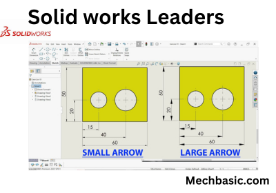
- You can customize the style of leader lines, such as adjusting the arrow size, changing the leader type (straight or curved), and controlling the leader’s line type and thickness.
- You can also add multiple leaders to a single annotation or dimension for clearer communication.
Leader Options and Settings
- Leader Style Options: You can customize how leaders behave in SolidWorks by adjusting settings found under the Document Properties > Annotations > Leaders.
- Leader End Style: You can choose between different arrow styles, such as closed arrowheads, open arrowheads, or even no arrowhead.
- Multiple Leaders: You can add multiple leader lines to the same annotation for clarity in complex drawings.
Leader Management Tips
- Avoid Overcrowding: Make sure leaders are clear and don’t overlap with other annotations or geometry in the drawing.
- Use Multiple Leaders Sparingly: Too many leaders connected to one feature can make the drawing difficult to read. Keep it clean and well-organized.
Leaders are an essential tool for communicating complex information in SolidWorks drawings, especially in detailed engineering or manufacturing environments.
Importance of Using Leaders in Solidworks:
- Clarity and precision.
- Enhancing Readability.
- Improving Communication.
- Consistency in documentation.
- Efficiency in interpretation.
- Flexibility and adaptability.
- Professionalism in design.
- Compliance with Drawing Standards.
- Ease of Editing.
In summary, leaders are crucial in SolidWorks and any technical drawing for ensuring that annotations are clearly linked to the appropriate features, enhancing the readability and clarity of the drawing, and helping prevent errors in manufacturing or assembly.
They also contribute to the professionalism and compliance of the design.