Taper turning is a lathe operation used to produce a conical surface by gradually reducing or increasing the diameter of a rotating workpiece along its length. This creates a uniform taper instead of a straight cylindrical shape.
It is commonly used for components such as machine tool spindles, shafts, and fitting parts, and can be performed using methods like compound slide movement, tailstock offset, or CNC programming. Taper turning ensures accurate angles and smooth surface finishes.
In this article:
- Taper Turning
- 1. Definition
- 2. Purpose of Taper Turning
- 3. Taper Terminology
- 4. Principle of Operation
- 5. Methods of Taper Turning
- 5.1 By Swiveling the Compound Rest
- 5.2 By Tailstock Set-Over Method
- 5.3 By Taper Turning Attachment
- 5.4 By Form Tool Method
- 6. Tools Used
- 7. Cutting Parameters
- 8. Procedure of Taper Turning (General)
- 9. Advantages
- 10. Limitations
- 11. Applications
- 12. Safety Precautions
- 13. Difference Between Plain Turning and Taper Turning
- 14. Difference Between Step Turning and Taper Turning
- Other courses:
Taper Turning
1. Definition
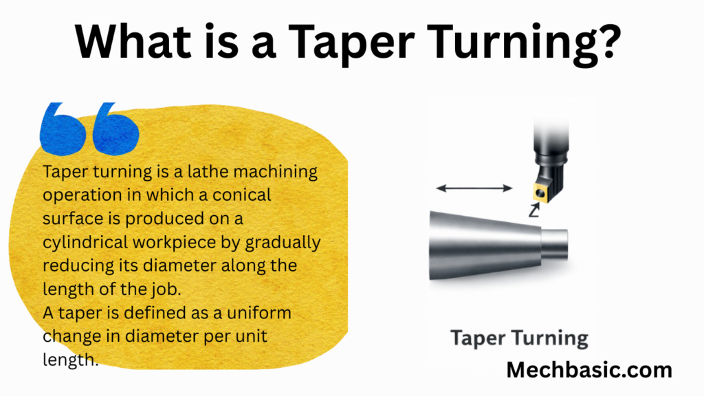
Taper turning is a lathe machining operation in which a conical surface is produced on a cylindrical workpiece by gradually reducing its diameter along the length of the job.
A taper is defined as a uniform change in diameter per unit length.
2. Purpose of Taper Turning
Taper turning is carried out to:
- Produce conical surfaces for machine elements
- Ensure self-locking or easy assembly
- Achieve accurate mating parts
- Improve alignment and power transmission
3. Taper Terminology
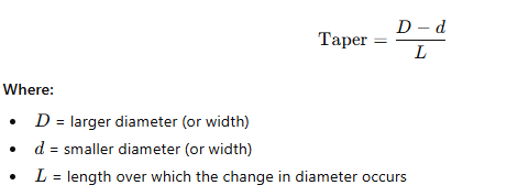
- Taper
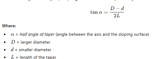
- Half Taper Angle (α)
- Included Taper Angle

4. Principle of Operation
- The workpiece rotates in the lathe.
- The cutting tool is fed at an inclined angle to the axis of rotation.
- Material removal occurs progressively, resulting in a conical shape.
5. Methods of Taper Turning
5.1 By Swiveling the Compound Rest
Description:
- The compound rest is swiveled to the half taper angle.
- Tool is fed manually along the compound slide.
Advantages:
- Simple and accurate for short tapers
- No special attachment required
Limitations:
- Not suitable for long tapers
- Manual feed only
Applications:
- Short internal and external tapers
- Precision work
5.2 By Tailstock Set-Over Method
Description:
- The tailstock is offset from the lathe axis.
- Workpiece axis becomes inclined.
- Tool moves parallel to the bed, producing taper.
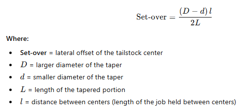
Set-over Calculation:
Advantages:
- Suitable for long, small-angle tapers
- Automatic feed possible
Limitations:
- Only for external tapers
- Alignment of centers affected
5.3 By Taper Turning Attachment
Description:
- Special attachment guides tool at required angle.
- Cross-slide movement is controlled by attachment.
Advantages:
- Accurate and repeatable
- Suitable for long and steep tapers
- Automatic feed possible
Limitations:
- Additional cost
- Setup time required
5.4 By Form Tool Method
Description:
- Tool has the exact taper profile.
- Tool is fed radially into the workpiece.
Advantages:
- Fast operation
- Good for mass production
Limitations:
- Only for short tapers
- High cutting force
- Tool wear is significant
6. Tools Used
- Single-point turning tool (HSS or carbide)
- Boring tool (for internal taper)
- Form tool (for short tapers)
- Taper gauges and sine bars (for inspection)
7. Cutting Parameters
- Cutting Speed: Lower than straight turning
- Feed: Moderate to low
- Depth of Cut: Light cuts for accuracy
8. Procedure of Taper Turning (General)
- Study drawing and calculate taper angle
- Select suitable taper turning method
- Mount workpiece securely
- Set tool at center height
- Adjust compound rest / tailstock / attachment
- Perform rough cuts
- Perform finishing cut
- Measure taper using micrometer or taper gauge
9. Advantages
- Produces accurate conical surfaces
- Essential for precision fits
- Different methods suit different applications
10. Limitations
- Setup time is high
- Accuracy depends on method and operator skill
- Tool wear affects taper angle
11. Applications
- Morse tapers
- Lathe centers
- Spindles
- Drill shanks
- Machine tool components
12. Safety Precautions
- Secure workpiece properly
- Avoid excessive depth of cut
- Check tailstock alignment after operation
- Use cutting fluid if required
13. Difference Between Plain Turning and Taper Turning
| Plain Turning | Taper Turning |
|---|---|
| Uniform diameter | Gradually changing diameter |
| Tool feed parallel to axis | Tool feed at an angle |
| Cylindrical surface | Conical surface |
14. Difference Between Step Turning and Taper Turning
| Step Turning | Taper Turning |
|---|---|
| Sudden change in diameter | Gradual change |
| Produces shoulders | Produces conical surface |
Other courses: