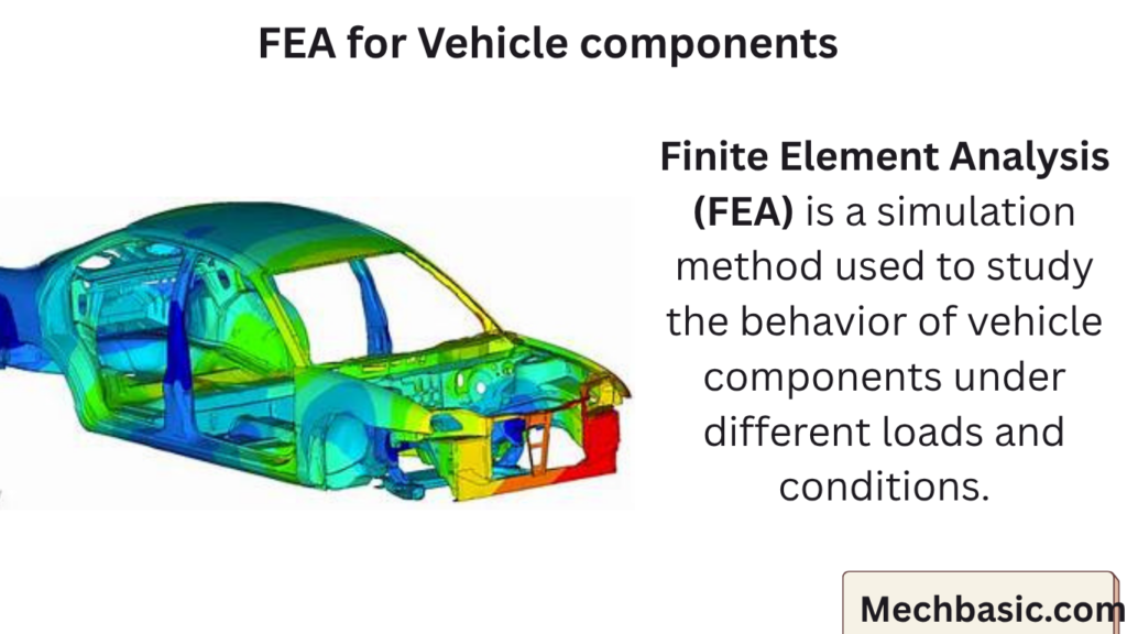
Finite Element Analysis (FEA) is a simulation method used to study the behavior of vehicle components under different loads and conditions.
It helps engineers analyze stress, strain, and deformation in parts like chassis, engine, and suspension systems.
Using tools like ANSYS and Abaqus, FEA improves safety, performance, and durability before physical testing.
In this article:
FEA for Vehicle components
Finite Element Analysis (FEA) is one of the most important engineering tools used in automobile design to predict how vehicle components behave under real-world conditions—without physically building and testing every part.
What is FEA?
FEA is a numerical method used to solve complex engineering problems by dividing a component into small elements (mesh) and analyzing their behavior.
It is based on the concept of the Finite Element Method.
A big problem (vehicle component) → broken into small pieces → solved mathematically → combined for overall result
Why FEA is Important in Automobile Engineering
- Reduces need for physical prototypes
- Improves safety and reliability
- Saves cost and development time
- Helps optimize weight (important for EVs)
- Detects failure before manufacturing
Steps in FEA for Vehicle Components
1. Geometry Creation
- 3D model is created using CAD tools like:
- CATIA
- Siemens NX
2. Meshing
- The model is divided into small elements (mesh)
- Types:
- Tetrahedral elements
- Hexahedral elements
👉 Finer mesh = more accurate results (but more computation)
3. Material Properties
Assign properties such as:
- Young’s modulus
- Poisson’s ratio
- Density
- Yield strength
4. Boundary Conditions
Define real-world conditions:
- Loads (forces, pressure)
- Constraints (fixed supports, joints)
- Contact between parts
5. Solving
The software calculates:
- Stress
- Strain
- Deformation
- Temperature (if thermal analysis)
Tools used:
- ANSYS
- Abaqus
6. Post-Processing
Results are visualized using:
- Color plots (stress/strain distribution)
- Graphs and animations
👉 Engineers interpret results and improve design.
Types of FEA in Vehicle Components
1. Structural Analysis
Checks strength and deformation.
Used for:
- Chassis
- Suspension arms
- Engine mounts
👉 Ensures components don’t fail under load.
2. Crash Analysis
Simulates accidents.
Used for:
- Car body
- Crumple zones
- Airbag systems
👉 Improves passenger safety.
3. Thermal Analysis
Studies heat distribution.
Used for:
- Engines
- Brakes
- Battery systems (EVs)
4. Fatigue Analysis
Checks life cycle under repeated loading.
Used for:
- Suspension systems
- Rotating parts
👉 Predicts when a component will fail.
5. Modal Analysis
Studies vibration characteristics.
Used for:
- Engine components
- Vehicle body
👉 Helps reduce noise and vibration.
6. CFD (Fluid Analysis)
Often integrated with FEA.
Used for:
- Aerodynamics
- Cooling systems
Examples of Vehicle Components Analyzed Using FEA
1. Chassis/Frame
- Load-bearing capacity
- Crash resistance
2. Suspension System
- Stress in springs and control arms
- Fatigue life
3. Engine Components
- Thermal stress
- Vibration
4. Brake System
- Heat generation
- Wear analysis
5. Body Panels
- Impact resistance
- Aerodynamics
Typical Outputs of FEA
- Stress distribution (Von Mises stress)
- Displacement/deformation
- Factor of Safety (FOS)
- Temperature distribution
- Fatigue life cycles
Advantages of FEA in Automobile Industry
- Accurate prediction of real behavior
- Reduces testing cost
- Faster product development
- Safer and optimized designs
- Supports lightweight design
Limitations
- Requires skilled engineers
- Results depend on assumptions
- High computational cost
- Errors possible with poor meshing or boundary conditions
Summary
FEA is like testing a car part inside a computer:
- Apply forces
- See where it bends or breaks
- Fix it before building the real part
Real Industry Workflow
- CAD model → (CATIA/NX)
- Import to FEA software → (ANSYS/Abaqus)
- Apply loads & conditions
- Run simulation
- Optimize design
- Finalize for manufacturing
Other courses: